ESP32
MCU - ESP32 S3
We will use the DFRobot Firebeetle 2 ESP32 S3 development board as the controller MCU:
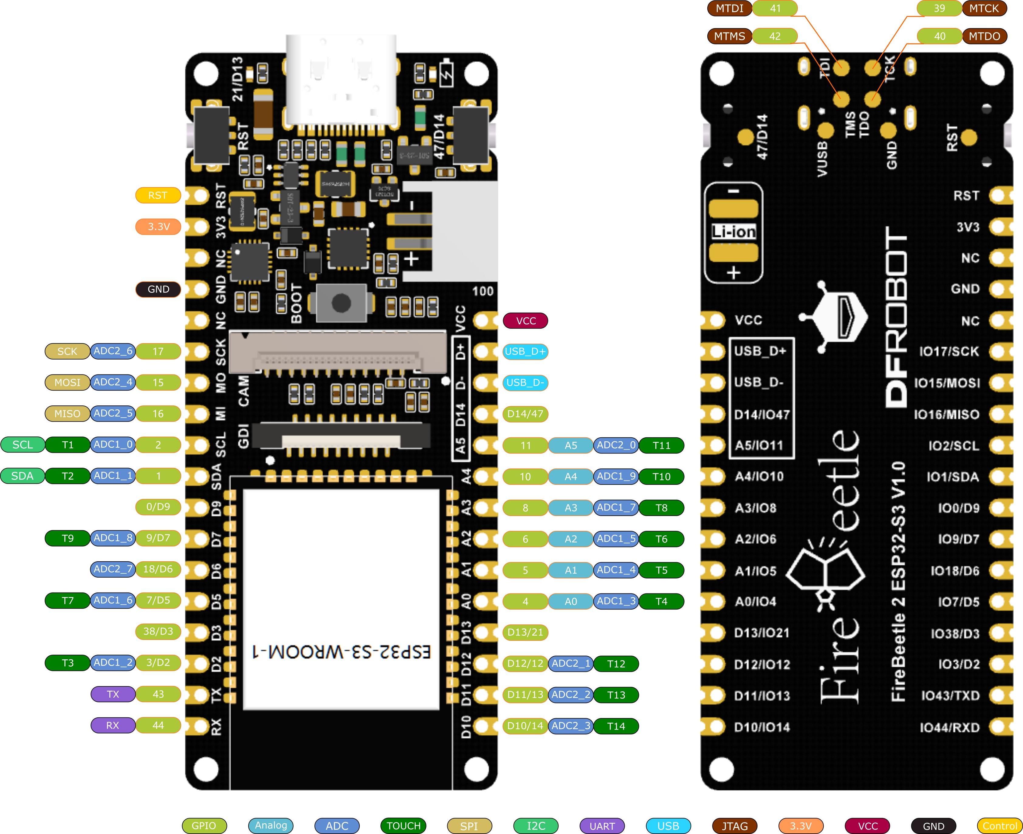
It might be a bit overkill, but this ESP32 board at least has the charging circuit and good documentation. As we don’t have that much room for the boards, we opt to solder all connections directly to the board. This means that we have to be sure which connections we are making!
HAT connection
The Waveshare HAT uses a 3 or 4 line SPI, we opt for the (regular) 4 line SPI. Next to the SPI interface, some other pins are needed:
| Waveshare HAT | ESP32 | Pin | Description |
|---|---|---|---|
| PWR | D12 | 12 | Power signal to e-Paper |
| BUSY | A1 | 5 | Busy signal from e-Paper |
| RST | D11 | 13 | Reset pin of e-Paper |
| DC | D10 | 14 | Data / Command selection |
| CS | A3 | 8 | SPI Chip Select |
| CLK | SCK | 17 | SPI Clock |
| DIN | MOSI | 15 | SPI Master Output Slave Input |
| MISO | 16 | SPI Master Input Slave Output (not used) | |
| GND | GND | GND | Ground |
| VCC | 3V3 | 3V3 | Power source |
| A0 | 4 | Analog input pin for voltage measurement | |
| T10 | 10 | Touch pin |
The second screen should also have some pins:
| Waveshare HAT | ESP32 | Pin | Description |
|---|---|---|---|
| PWR | D7 | 9 | Power signal to e-Paper |
| BUSY | A2 | 6 | Busy signal from e-Paper |
| RST | D6 | 18 | Reset pin of e-Paper |
| DC | D5 | 7 | Data / Command selection |
| CS | D3 | 38 | SPI Chip Select |
Pins to avoid:
| ESP32 | Pin | Description |
|---|---|---|
| D9 | 0 | Boot |
| D2 | 3 | JTAG boot |
| D14 | 47 | User key (button on board) |
| D13 | 21 | LED on board |
This means that 4 pins are shared (3V3, GND, SCK, MOSI).
This Firebeetle doesn’t seem to have a way to measure battery status :-(. We could make a small circuit that does just that, as described in this reddit post. According to this blog the resistor should be between 10k and 242k. We choose 220k resistors.
Connection via the breakout board
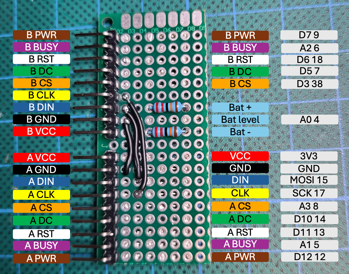
The breakout board is directly connected to the MCU, with combined connections for GND, 3V3, SPI SCK and SPI MOSI. Via the breakout board it is easy to connect both displays, using the 9 pins cable (colors correspond to the colors of the cable).
Pinout testing board
To test the software, I will first use a different WROOM-32 ESP board, with this pin configuration:
| Color | Waveshare HAT | ESP32 | Pin | Description |
|---|---|---|---|---|
| Brown | PWR | GPIO13 | Power signal to e-Paper | |
| Purple | BUSY | GPIO12 | Busy signal from e-Paper | |
| White | RST | GPIO14 | Reset pin of e-Paper | |
| Green | DC | D10 | GPIO27 | Data / Command selection |
| Orange | CS | CS0 | GPIO5 | SPI Chip Select |
| Yellow | CLK | CLK | GPIO18 | SPI Clock |
| Blue | DIN | MOSI | GPIO23 | SPI Master Output Slave Input |
| MISO | GPIO19 | SPI Master Input Slave Output (not used) | ||
| Black | GND | GND | GND | Ground |
| Red | VCC | 3V3 | 3V3 | Power source |