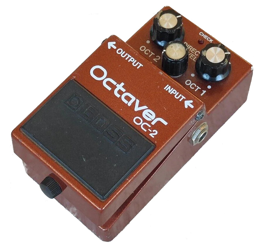
Boss OC-2 Octaver
The Boss OC-2 Octaver started the widespread use of an octave-down pedal. It was first introduced in 1982 and continued in production till 2003 when it was replaced by the digital OC-3. As made in the pre-digital era, the OC-2 was a pure analog pedal.

A simplified version of the circuit can be found here. The workings of this circuit is explained in the Stompboxology Frequency Division & Subharmonic Synthesis (volume 13, number 3).
The OC-2 circuit is made out of a number of distinct subcircuits:
- The input stage (buffer)
- The analyser (tracking the input signal)
- The sub octave creator (appearing twice, to create the -2 octave)
- The output stage (mixing)
Input stage
The input stage raises the signal to the virtual ground (as we use a single supply, a virtual ground is used between the actual ground and the 9V supply voltage) and amplifies the input signal by a factor of around 5.
The input stage operates as a high pass filter, but the cut-off point is very low, so both phase shift and amplitude are not effected at frequencies >50Hz.
Analyser stage
The analyser stage looks at the input signal and “detects” the fundamental frequency. After that, this fundamental is used as an input to a descrete flip-flop stage that creates a square wave that is half the fundamental frequency, and a square wave that is a quarter of the fundamental frequency. These control frequences are used in the sub octave creator stages.
The first part of the analyser stage is filtering out the fundamental frequency. It starts with a low pass filter (stage 1) and continues with a circuit that creates two square waves: one that has peaks at the top of the output of stage 1, and an inverted one that has peaks at the bottom of the output of stage 2, as is depicted in the figure below.
The square wave are generated by the comparators (the last two LM324 OpAmps). These comparators compare the original signal with its peaks. These peaks are created by the first two LM324 OpAmps. In the figure below, the signal that is used for the peak detectors is presented and the output of the peak detectors. These signals are filtered before the comparators (not shown).
The first part of the CD4013 is used to create a square wave that ideally follows peaks of the original signal, so it is in 90 degrees phase of the original. The second part of the CD4013 is used to half the original frequency. The original circuit continues with a BA634, replaced in the simplified version with a CD4027. This simply halfs the frequency again, for the -2 octave.
As the flip-flow will set and reset at the rising edge of the square wave, ideally this should correspond with the peaks of the original input wave. This is pretty ok for 440Hz, as depicted below, but falls short at 220Hz or 880Hz! The graph below shows the original input signal (in red) and the corresponding square wave at half the frequency. At 220Hz the square wave is too early, at 880Hz the square wave lags behind.
Sub octave creator
The sub octave is generated by raising the input just above the virtual ground (using the capacitor and diode) and then multiply it with 0.5 when the transistor is turned off, and with -0.5 when the transistor is turned on. The original OC-2 circuit doesn’t trim the anode of the diode, so the input is actually a (germanium) diode drop below the virtual ground. The best result is created when the lowest point of the raised input is precisely at the virtual ground. This is achieved by the extra trimming resistor, compensating for the diode drop (we could probably use a silicon diode with a larger diode drop, and compensate a bit more).
Above, non-trimmed result: some part of the waveform is below the virtual ground, the different parts don’t match correctly.
Above, trimmed result: the waveform is exactly at the virtual ground, the different parts match correctly. If we would “overshoot” the waveform, we would also have unmatched parts.
It should be noted that it is very important that the control signal is in the correct phase with the input signal, or the signal would be chopped at an incorrect place, resulting in wavefolding, e.g.: more harmonic overtones.