Smoke detector repurposed
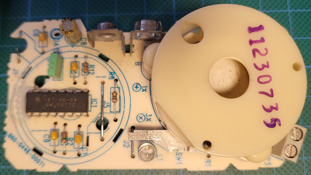
I found an old smoke detector that should work perfectly as the siren for the circuit. The plastic cilinder to the right is the container for the piezo buzzer, that will oscillate at its resonate frequency. These buzzers have three wires: one gives a feedback signal that is used to set the frequency just right.
The IC is a custom made IC for these kinds of smoke detectors. The markings are a bit weird, but looking on the internet, it seems equal to the MC14468. The IC has one leg that is not connected to the PCB, but was connected to the detector. When we pull down this pin, the buzzer is in its OFF state (no smoke), but if we set some voltage on this pin, the buzzer will sound (smoke!). The pin has a very high impedance, so very little current will flow. This is ideal for our purpose, so we could simple send the signal from the motion detector to this circuit!
The circuit itself is powered by a 9V battery, it also works with 6V (directly from the whole circuit), but we keep it like it is, so we have two independent power sources.
IC Pins
Pins 1,4,9 (GND)
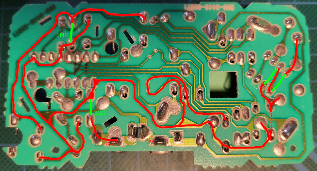
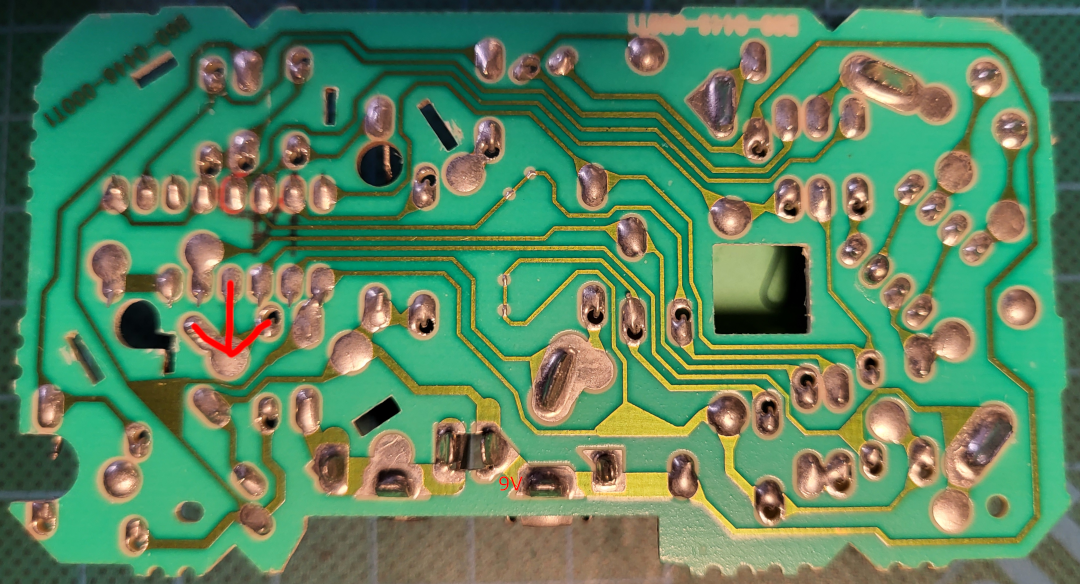
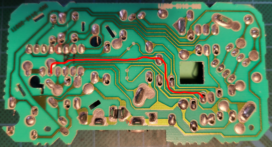
The ground net is protected by a 33Ω resistor, pins 1, 4 and 9 are conntected to ground. The detector is grounded via a 1M resistor. So we can use this resistor as the pull-down resistor for the detector-pin (pin 15).
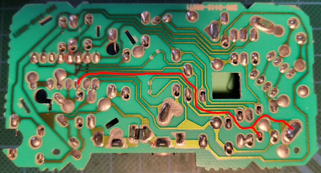
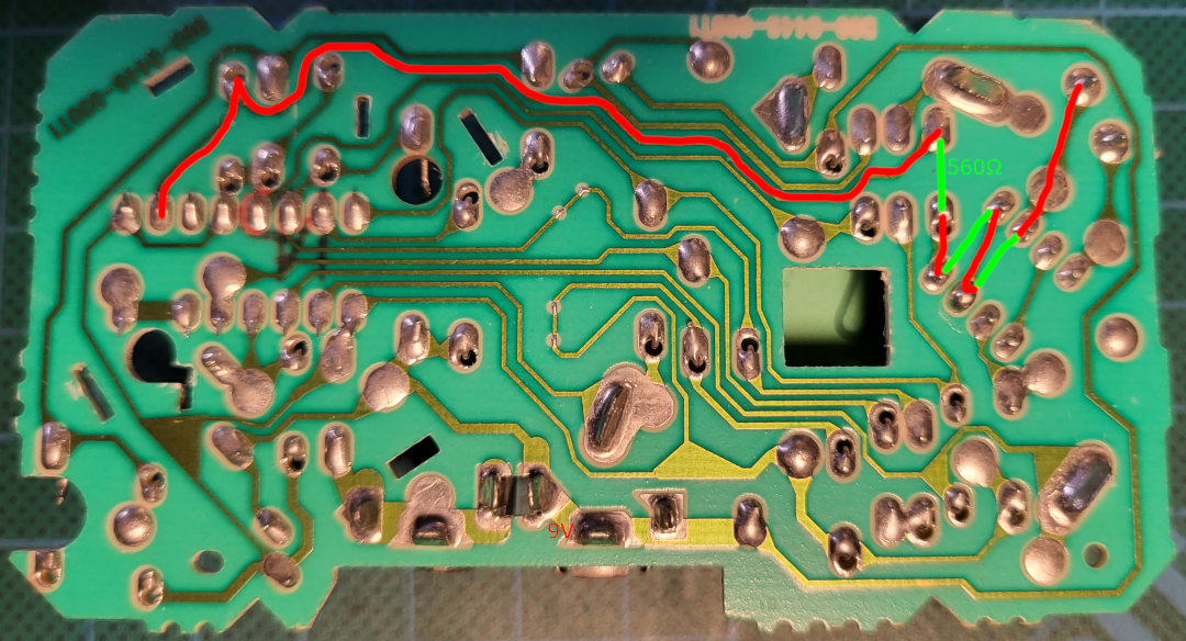
Pin 6 (9V)
The 9V net is connected to IC, the LED and the test-switch.
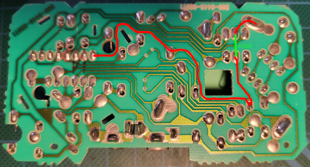
Pin 5 (LED)
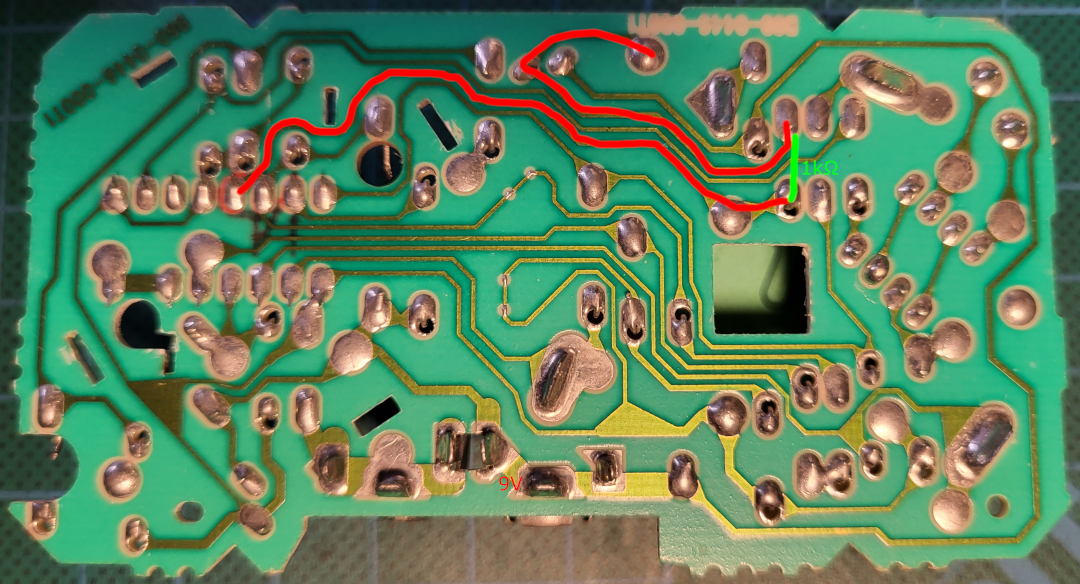
Pin 5 controls the LED.
Pin 11 (piezo silver)
Pin 11 is connected to the silver part of the piezo buzzer.
Pin 10 (piezo brass)

Pin 11 is connected to the brass part of the piezo buzzer.
Pin 8 (piezo feedback)
Pin 8 is connected to the feedback wire of the piezo buzzer.
Pin 2 (I/O)
Pin 2 is the optional I/O with other smoke detectors. Although this part of the circuit wasn’t used, the terminals for the wires to other smoke detectors are available! An unknown component is hidden below the piezo buzzer, it is not clear what this component does, maybe some galvanic isolator??
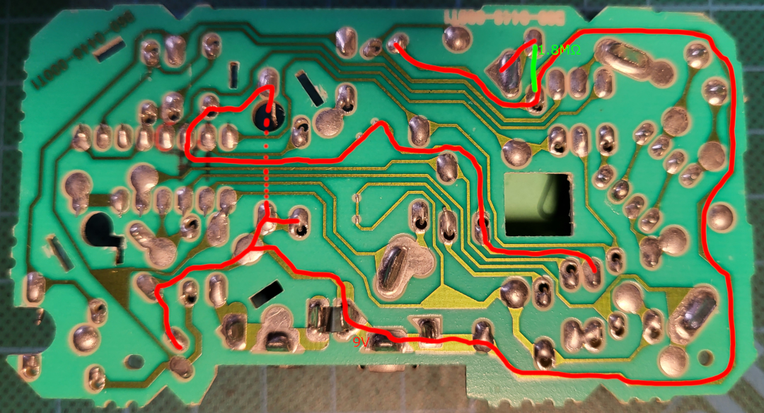
Pin 7
Timer resistor. This pin, in combination with pin 12 sets the frequency of the oscillation and timer.
Pin 12
Oscillator capacitor. This pin, in combination with pin 7 sets the frequency of the oscillation and timer.
Pin 13
This pin sets the sensitivity of the device.
Pin 14, 16

These pins are guard pins for pin 15, as this pin is very sensitive when used in its “normal” function for detecting any change.