Oktava MK-12 original
The pictures below depict the PCB with the original components. The one with the most components is vertically flipped, make the top of both images the same.
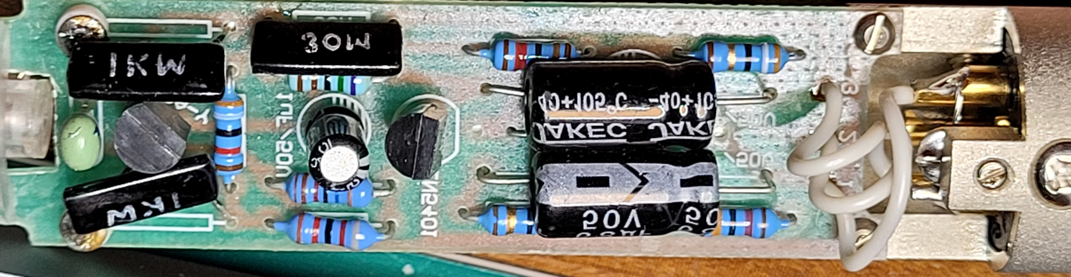
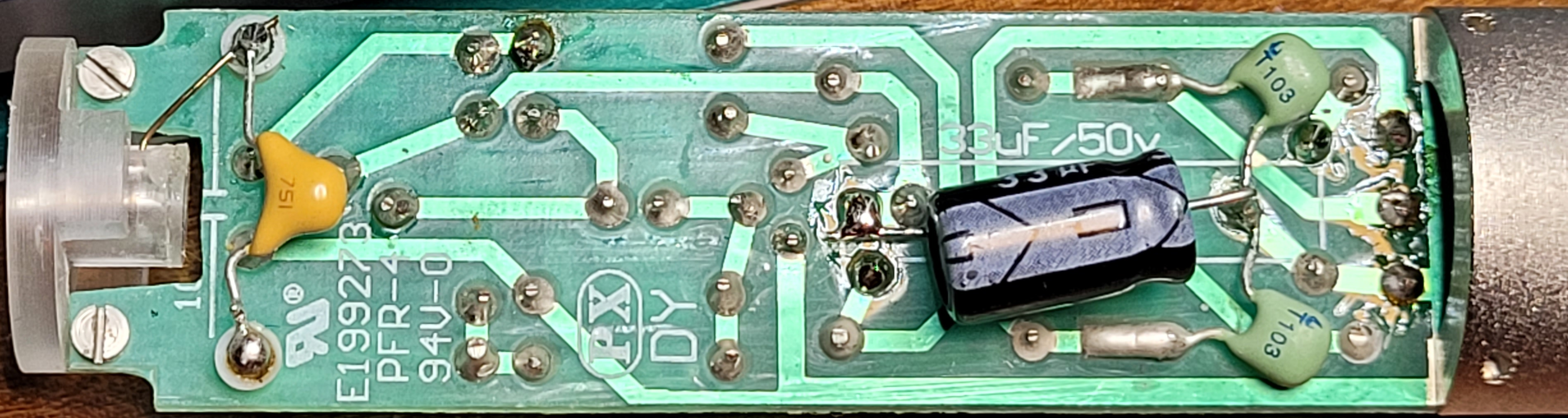
One interesting observation is that the PCB contains radial capacitors, but the PCB itself expects axial capacitors, which is more logical, considering the available space. A lot of different versions of the internals of this microphone can be found on the internet. It seems that the first versions of this microphone did contain axial capacitors. These original versions are infamous regarding the flimsy PCB. The new PCBs looks more robust, but they didn’t bother to change the layout of the circuit for the new radial capacitors.
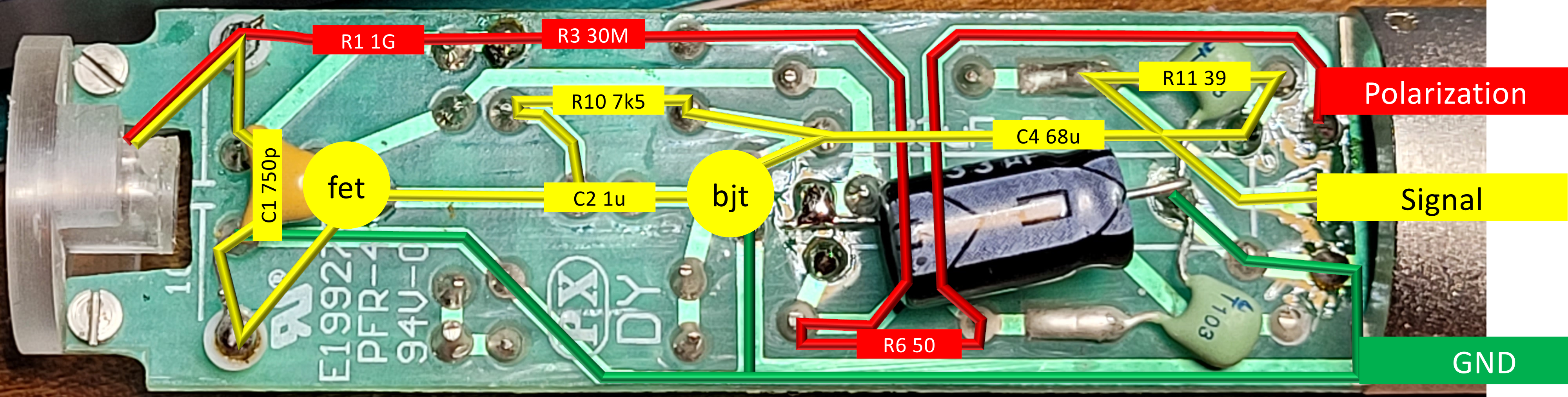
The picture above shows the signal flow. The capsule is polarized via XLR pin 2. The actual signal is send back via XLR pin 3. XLR pin 1 is the ground pin. The PCB contains two 1G ohm resistors. One resistor is used to polarize the capsule, the other sets the bias for the gate of the FET transistor.
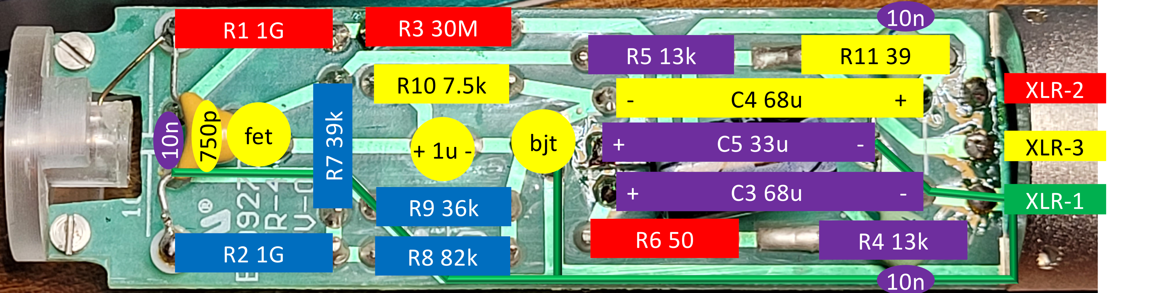
The first guess was that one of the large capacitors was faulty, but it actually was the 1G ohm resistor at the gate of the FET transistor that was faulty. The picture below depicts all the components.
| Comp | Value | Description |
|---|---|---|
| Q1 | 2SK30A-Y N-Channel FET | voltage controlled |
| Q2 | 2N5401 PNP BJT | current controlled, voltage source |
| C1 | 750pF Ceramic | Signal input AC coupling cap |
| C2 | 1uF Elco 50V 4x8 mm | Signal stage AC coupling cap |
| C3 | 68uF Elco 50V 6x12 mm | Polarization filter cap |
| C4 | 68uF Elco 50V 6x12 mm | Signal output AC coupling cap |
| C5 | 33uF Elco 50V 6x12 mm | Supply voltage filter cap |
| C6,C7,C8 | 10nF Ceramic | Filter cap |
| R1 | 1G Thick film | Polarization resistor |
| R2 | 1G Thick film | Bias resistor for Q1 |
| R3 | 30M Thick film | |
| R4,R5 | 13k | Impedance matching resistors |
| R6 | 50 | |
| R7 | 39k | Bias resistor |
| R8 | 82k | Bias resistor |
| R9 | 36k 5ppm? | Bias resistor |
| R10 | 7.5k | Signal coupling resistor |
| R11 | 39 |