Vocoder case
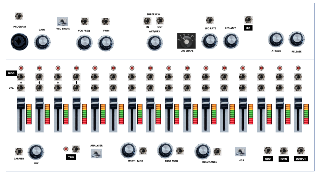
The case consists of three separate sections:
- The filter modulation section (FM);
- The program input section (PI);
- The sound source section (SSI, SS-LFO, SS-NOISE, SS-VCO, SS-ENV);
- The filter bank control section (FC).
The codes for these sections are cross-referenced in the design, to make sure all controls are accounted for.
FM - Filter modulation section
The filter modulation section consists of three knobs and three CV jack inputs:
- FREQ MOD: Frequency modulation knob and jack;
- WIDTH MOD: Q (bandwidth) modulation knob and jack;
- RESONANCE: Filter resonance knob and jack.
PI - Program input section
The program input section consists of two sound source inputs, a knob and a switch:
- PROGRAM: XLR microphone input;
- PROGRAM: jack line input;
- GAIN: gain level of the preamp;
- ANALYSER: switch to select either the trigger section or the vocoder analyser section.
Sounde source section
SSI - Sound Source Input
The sound source input is a single input jack:
- CARRIER: jack line input.
SS-LFO Sound source, LFO
The LFO section consists of one input jacks, two knobs, one output jack and one selector dial:
- LFO RATE: LFO Frequency knob and jack;
- LFO AMT: LFO Modulation amount knob;
- LFO SHAPE: LFO Waveform selector;
- LFO: The LFO Signal output jack.
SS-NOISE Sound source, noice
The NOISE section consists of a knob and a switch:
- MIX: Mix knob between VCO and the NOISE or Carrier input;
- HISS: switch to turn on the routing of noise to channels 15 and 16 of the carrier filter bank.
SS-VCO Sound source, oscillator
The VCO section consists of 4 input jacks, 1 output jack, 2 knobs and 1 selector switch (3 settings)
- VCO FREQ: 1v/o frequency input jack and knob;
- VCO PWM: input jack to modulate the pulse width (for square wave);
- VCO FM: input jack for frequency modulation;
- VCO SHAPE: VCO Waveform selector (Triange, Sawtooth, Square)
- SUPERSAW IN: Supersaw input jack;
- SUPERSAW OUT: Supersaw output jack;
- SUPERSAW Wet/dry knob;
SS-ENV Sound source, envelope generator
THE Envelope generator section consists of 2 knobs, 1 input jack and 1 button:
- TRIG: input jack to trigger the envelope generator;
- TRIG: button to trigger the envelope generator;
- ATTACK: knob to set the attack duration;
- RELEASE: knob to set the release duration;
FC - Filter bank control section
The filter bank control section consists of 32 output jacks, 16 input jacks and 16 sliders:
- PROG: 16 envelope follower output jacks;
- LEVEL: 16 sliders to control the VCA output level per channel;
- VCA: 16 input jacks to the VCA CV;
- ODD: The mix of all odd VCA output levels;
- EVEN: The mix of all even VCA output levels;
- OUTPUT: The final output, mix of all VCA output levels.