12AX7 Triode
The 12AX7 (also called ECC83S) tube used in the AC5 is a JJ Electronic tube, manufactured in the tube factory in Čadca, Slovakia. JJ Electronic is actually only founded in 1993, but they use the old machinery from the old Sovjet-era TESLA company. Not that many tube factories exists nowadays, and most brands are actually rebranded tubes from one of a very few still existing factories.
The pinout and most fundamental characteristics can be found in the JJ ECC83S datasheet:
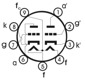
| Pin | Name | Description |
|---|---|---|
| 1 | a’ | Anode (plate) 2nd tube |
| 2 | g’ | Grid 2nd tube |
| 3 | k’ | Cathode 2nd tube |
| 4 | f | Filament heater pin |
| 5 | f | Filament heater pin |
| 6 | a | Anode (plate) 1st tube |
| 7 | g | Grid 1st tube |
| 8 | k | Cathode 1st tube |
| 9 | fc | Center tap filament |
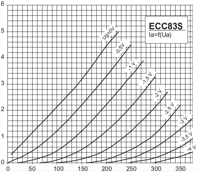
The datasheet provide a diagram with the static anode characteristic curves:
12AX7 tube analysis
For tube analyses, the diagram below gives the usual structure. The 12AX7-mz Rydel model is used for this simulation as it gives the most correct model (as we will see) for the 12AX7.

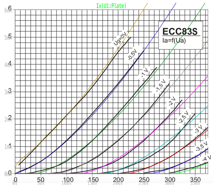
The result of this analyses, when plotting the current of the Anode, gives:

This calculated result is actually quite good when you compare it to the plot from the datasheet, as is clear when you overlay the original diagram with the calculated one:
But we need to find out a bit more: we want to see how the model performs three different situaties:
- Normal operation, at the limits of its headroom (centre biased at -2V);
- Simulate cut-off clipping by cold biasing;
- Simulate grid-current clipping by warm biasing.
Normal operation
We use the circuit as described by the valve wizard for easy comparison. The first thing we have to find out, is the bias resistor. If we want to obtain a bias voltage of Vgk = -2V, from the diagram we can find out that the quiescent anode current will be 0.80mA at Va = 220V. We get this number by using the .meas operation in which we use the load line with plate resistor Ra = 100k and plate voltage = 300V (the blue line). The red line visualizes the maximum power the tube can handle, you don’t want to get near this area.

From this, we can calculate the value of the bias resistor, using the valve wizard’s guidelines: Rk = Vk/Ia = 2/0.80 = 2500 ohm. As the valve wizard states: this is not the end story, because the actual load line resistor will now not be R = Ra = 100k, but R = Ra+Rk = 102500. This will change the value of Rk a bit, but not by very much. The actual value for Rk would be 2524 Ohm.

We use a 4V p-p input source (2V AC amplitude). The result of this circuit is presented in the graph below. Vk = 2.12V, the current of the plate reaches 1.9mA and the plate voltage goes from 106V to 300V.

But wait: why does Vk = 2.12V? This is because of the self-biasing of the cathode biased network, in combination with the value of the cathode capacitor. Without the capacitor, the Vk would mimic the waveform of the grid. This is filtered out by the capacitor, but this has some impact on Vk. The graph below give Vk with values of 1u, 10u, 100u and 1000u for Ck.

Cut-off clipping
Cut-off clipping is simulated by cold biasing the circuit with Rk = 4k7.

Grid-current clipping
Grid-current clipping is simulated by warm biasing the circuit with Rk = 730.

As is clearly visible (and expected), the input signal itself is clipping, not so much the output.