ECC99 Triode
The ECC99 tube used in the AC5 is a JJ Electronic tube, manufactured in the tube factory in Čadca, Slovakia. JJ Electronic is actually only founded in 1993, but they use the old machinery from the old Sovjet-era TESLA company. Not that many tube factories exists nowadays, and most brands are actually rebranded tubes from one of a very few still existing factories.
Although the tube is normally used as a preamp tube, in a small amplifier as the AC5, it can be used as a dual power amp tube. The pinout and most fundamental characteristics can be found in the JJ ECC99 datasheet. It is exactly the same as the well known 12AX7:
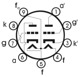
| Pin | Name | Description |
|---|---|---|
| 1 | a’ | Anode (plate) 2nd tube |
| 2 | g’ | Grid 2nd tube |
| 3 | k’ | Cathode 2nd tube |
| 4 | f | Filament heater pin |
| 5 | f | Filament heater pin |
| 6 | a | Anode (plate) 1st tube |
| 7 | g | Grid 1st tube |
| 8 | k | Cathode 1st tube |
| 9 | fc | Center tap filament |
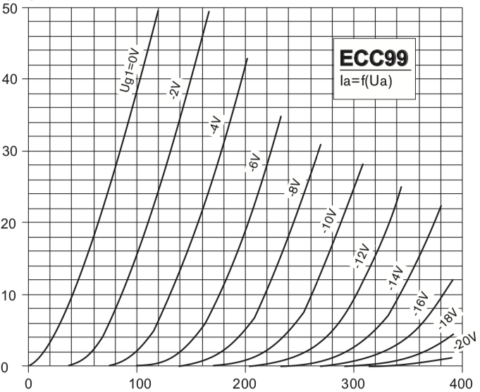
The datasheet provide a diagram with the static anode characteristic curves:
12AX7 tube analysis
For tube analyses, the diagram below gives the usual structure.

The result of this analyses, when plotting the current of the Anode, gives:

Although not exactly the same as the graph from the datasheet, it’s pretty close. When you compare it to the 12AX7, it is obvious that the ECC99 can produce a lot more power than the 12AX7.
Push-pull use
The ECC99 dual triode tube is used in a push-pull operation. So let’s find out how this works. The circuit below is used to perform our calculations.

Three values are need to be calculated:
- The plate voltage (B+);
- The Cathode resistor;
- The plate-to plate (Ra-a) impedance.
The plate voltage is set at 270V, so we start with that figure. At this figure, we can calculate the maximum bias current, this will be the crosspoint between the max watt for the ECC99 and 270V. As P = I * V, this results into: 3.5 = I * 270, I = 3.5W / 270V = 13.0mA. The grid bias voltage that corresponds with this figure is the point where the grid voltage line would cross that point. This point corresponds with Vgk = -10.4V. Total current accross one cathode resistor will be twice the plate current of one tube, so from this we can calculate Rk = -10.4V / (2*13.0mA) = 400 Ohm.
For push-pull operations, the actual load that is seen by each tube is:
- For a pure class A operation: 0.5 * Ra-a (both tubes are active);
- For a pure class B operation: 0.25 * Ra-a (only one tube is active, so only have of the winding of the transformer is used)
Let’s start with Ra-a = 12800 ohm. Class A operation results in a load-line with R = 6400 and class B operation results in a load-line with R = 3200. Because of the biasing, the load-line should be raised to the point that the load-line hits the bias point, as presented in the figure below.

As is clearly visible, the load-lines are in the danger-area. As Rob Robinette describes, this is possible but will drive the tubes to their max.
But…the actual Molly tube amp has a Rk = 270 Ohm. This will raise the Class-A load-line to a very high point inside the “warning area”. Some point can be made:
- Original, the max power of the JJ ECC99 was rated at 5W, which will reduce the danger area.
- The circuit diagram of the Molly states 250V plate voltage and 9V cathode voltage.
So let’s use these figures! Imax = 5.0W / 250V = 20mA. This gives Rk = 9.0V / (2x20.0mA) = 225 Ohm (100%) and Rk = 265 Ohm at 85%. So by using Rk = 270, the original design of the Molly circuit was perfectly in order. But while Rk=270 gives a power rating around 84% max at 5W, Rk-270 is actually around 120% max at 3.5W. The table below give the corresponding values for R at different power ratings:
| Power | 3.5W | 4.2W | 4.5W | 5.0W |
|---|---|---|---|---|
| 84% | 383 | 319 | 298 | 268 |
| 85% | 378 | 315 | 294 | 265 |
| 100% | 321 | 268 | 250 | 225 |
| 120% | 268 | 223 | 208 | 188 |
If we plot the load-lines using the figures from the Molly circuit (Va = 250V, Rk = 270, Vk = 9V, thus Ia = Ik = 9V / (2*270Ω) = 16.6mA, we get the following result. The blue line is the original 3.5W max power line, the red line is the 5.0W max power line. The dotted line indicates the bias point. The class-A load-line (purple) is precisely within the safe area, as is the class-B load-line. I suspect that the Molly circuit was designed for the 5.0W rating of the ECC99 tube and never redesigned for the lower wattage? As discussed in this google group, some state that the ECC99 sounds best near its max power ratings, so…
