AC5 Circuit
The circuit for the AC5 is, as you might expect, the circuit for the TT Molly kit. A single EF86 pentode is used as for the preamp input tube (as in the original AC4/AC10/AC15 and the very first AC30/4), followed by a 12AX7 dual triode tube for the phase inverter, going into the two parts of the ECC99 dual triode tube in a push-pull cathode biased configuration. The ECC99 is normally not used as a power tube, but in this small package, it delivers about 4 watts of power, as the original AC4.
And, in fashion with the original VOX AC2/AC4/AC6 (which are actually the same 4 watt amplifiers…), we simply call it the AC5.
This gives is a tube amplifier with an original AC30/4 preamp circuit with a penthode tube, and a push/pull cathode biased power amplifier circuit, as in all AC30s (but not in the original AC4!). The table below give the differences between the different amps. The AC5 doesn’t have a pentode power output stage, as the other Vox AC amps had, it uses a dual triode instead.
| Stage | “AC5” | Vox AC4 | Vox AC15 | Vox AC30/4 |
|---|---|---|---|---|
| Preamp | EF86 CB | EF86 CB | EF86 CB | EF86 CB |
| Phase inverter | 12AX7 LTAC | 12AX7 LTAC | 12AX7 LTAC | 12AX7 LTAC |
| Power output | ECC99 PPCB | EL84 SE | 2xEL84 PPCB | 4xEL84 PPCB |
(CB = Cathode Biased, LTAC = Long-Tail AC Coupled, SE = Single Ended, PPCB = Push-Pull Cathode Biased)
Power Transformer
The Power transformer is a 70mm x 35mm (DxH) toroidal transformer, TT T30 V2. The primary is universal with four taps 0-120-230-240 VAC (black, yellow, purple red wires). The secondaries are 200 VAC 0.085 mA (red) and 6.3 VAC 2A (green).

The SPICE model is the ideal representation of such a transformer. Values for the inductance are calculated by using the formula Lpri/Lsec = (Npri/Nsec)^2. The model uses the European 230 VAC rms 50Hz input voltage. This results into 230*√2 = 325 VAC peak to peak. I used an inductance calculator for toroids to get an estimate for the inductance of the primary windings, using 35mm for the radius of the transformer and 384 windings (a guess that works good for the needed ratio, the actual number of windings is probably some factor of 2 to 5 higher).
Rectifier and filter capacitors
The solid state full rectifier and filter capacitors are from the PSU Mini kit and placed on a separate PCB board, making it very easy separate the power from the rest of the circuit.

The PSU contains a solid state bridge rectifier. The capacitors across the diodes are added to filter out oscillation noise. The current SPICE model uses 1n4007 diodes. If UF5408 diodes are used, these capacitors might not be as necessary.
Filter capacitors C1 to C7 filter out any AC ripple from the rectifier. The different stages (B1, B2, B3) are made clearly visible in the diagram. Resistors R1, R2, R4 and R5 work as safety discharge resistors. Resistors R3 and R6 form an RC low-pass filter together with capacitors C5+C6 and C7, delivering increasingly cleaner DC voltage at B2 and B3 outputs.
Resistor Ramp is added to simulate the load of the amplifier as it is observed by the PSU (which gives B3 = 250V).
Input stage
The input stage circuit diagram is a bit confusing, because it makes use of the way the input sockets works: without a jack plugged in, the socket make a different connection than with a jack plugged in, as made visible in the figure below. The red line is the input signal (tip of the jack), the blue line the ground (sleeve of the jack). The green line displays the route that the signal also travels.
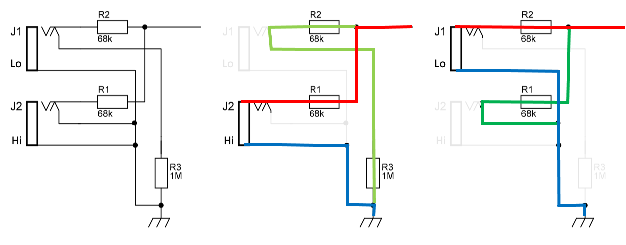
The actual circuits with a jack plugged into either the Lo(w) or Hi(gh) gain input sockets is displayed in the spice model below. The Low gain input uses a resistor devider network, so that the actual voltage that is received at the gate of the tube is half the original voltage. The High gain input doesn’t have a resistor divider network (theoretically it does, but the voltage drop of the 1Meg + 68k resistors is negligible). R2 (Lo) and R2+R3 (Hi) have a secundaire function: maintaining a ground reference for the grid (the green line). In most circumstances, a ground reference is available via the plugged in instrument so this is actually a safety measure. Without any reference to ground, the grid will gradually collect electrons traveling from the cathode to the plate, making it more positive and the pre amp won’t work any more. Without any jack plugged in, both paths to ground are active, maintaining the ground reference. A problem might occur when both the Hi and Lo sockets are used, because in that case the ground reference depends on the instruments plugged in.

Preamp stage
The preamp stage features an EF86 pentode tube, with is essentially identical to the circuits in the original AC15 and AC30, displayed in the spice model below.

Vin is connected to the input stage of the amplifier, so a 1068k resistor to ground (Hi input) or a 68k resistor to ground (Lo input) is connected to the control grid. The input stage also contains the 68k grid stopper resistor. The suppressor grid is directly connected to the cathode.
The cathode is biased to ground via a 2k2 resistor. Coupling capacitor C2 passes the AC signal from the preamp stage to the gain stage of the amplifier, filtering out the high DC voltage.
The gain of the preamp stage is around 180. More information and a SPICE model for the preamp can be found on the Preamp model page.
Gain stage
As the “gain” stage is actually around a potentiometer, it is actually an attenuation stage. But because the signal from the preamp is really hot, you might say that you add “gain”…

P1a and P1b represent the gain pot. In the position displayed in the circuit, the gain pot is fully “open”, which will still attenuate the signal by 25/(25+47) ≈ 35% (the resistor divider network with R22), resulting in a output voltage of 32V at an input voltage of 92V. The silver mila 500p condensator will allow to pass some high frequencies whatever position the pot is in.
Phase inverter
A long tail phase inverter with the two halves of a 12AX7 tube is used for this circuit, displayed in the spice model below:

The phase inverter has the classical AC coupled long-tailed pair topology as described by the valve wizard. Coupling capacitors C5, C7 and C8 passes the AC signal from the preamp stage to the gain stage of the amplifier, filtering out the high DC voltage.
Master volume and Cut stage
I’ve added the optional master-mod to the circuit, which enables full preamp distortion at a very low level. According to the description on the Tube-Town project description, a resistor divider network is already present, because the gain from the preamp would overdrive the ECC99 power tube to quickly. So actually two resister divider networks are present in this stage: one for the master volume (P3a/P3b and P3c/P3d) and a fixed one (R21/R14 and R20/R13). The master volume pot is a audiog (logaritmic) stereo potentiometer, so P3a/P3b will always have the same attenuation value as P3c/P3d. The gain from the preamp is reduced to half the amount, which can be even more reduced by using the master volume pot. The whole circuit is displayed in the spice model below:

Resistors R13 and R14 are not only part of this stage, but are also part of the self-biasing circuit for the push-pull power amp stage. The cut potentiometer P2 controls the amount of signal is passed by capacitor C9 (10n), filtering out some high frequencies. Because the wiper of the pot is connected to one of the other pins, the pot operates as a simple variable resistor: only resistor P2b has an effect on the circuit (the resistance of P2a in parallel with the wire always has a combined resistance of 0 Ohm). As the analysis of the Cut circuit shows, the value of 10n for capacitor C9 is a bit high. This will attenuate also the lower frequencies more, the the cut control as a whole will function more or less the same: as resistor P2b is opened, the frequency cut-off will also change, letting more low frequencies pass.
Power output stage
The power output stage uses a ECC99 tube and a Hammond 125C output transformer. It’s a classic push-pull cathode biased output stage. The circuit below show both parts (the B2+ high voltage is connected to the center tap of the transformer, this is need for the plate voltage!). Modeling the output transformer is not an easy task, we opt for just an ideal transformer to get the output transformer impedance correct, leaving out all the details from the real one, as explained in these videos (part 1, part 2) and this forum post.
The datasheet of the 125C OT states a plate-to-plate impedance of 12.8k Ohm at am 8 ohm load on the secundary (pins 4 and 6). From this, we can calculate the inductance ratio: it’s the same as the impedance ratio. In the same datasheet, the primary inductance is stated as 5.6H (unclear if this is plate-to-plate, we asume this is the case). This results in a secundary inductance of 3.5mH. The inductance of each half of the primary coil: (0.5*√5.6)^2 = 1.4H.

B2 is set at 270V (as obtained by the psu circuit simulation), Rspeaker = 8 Ohm is added as the load for the transformer.