Building the AC5
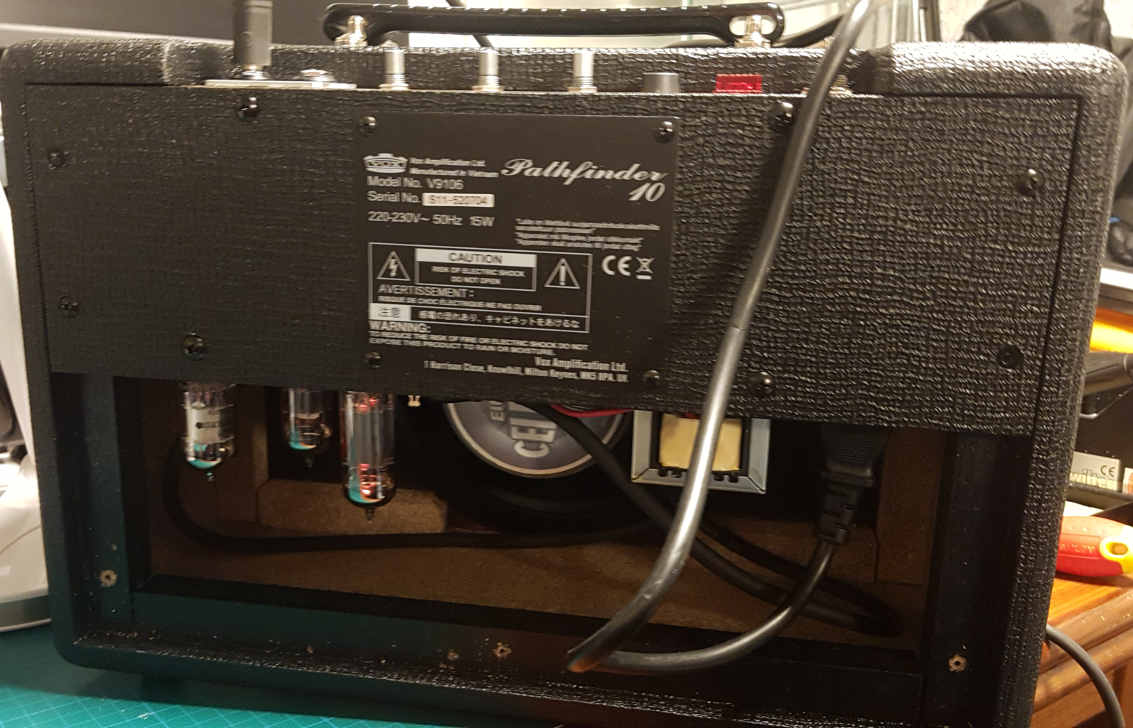
The build of this AC5 is visible in one picture: the back of the AC5. The front is still the same: a pathfinder 10. But the back shows the real deal:
- It’s a pathfinder (and as a fellow band member stated: “what does it say: CAUTION DON’T open???”);
- The VOX 6.5 speaker is replaced with a Celestion 8 inch speaker;
- It has tubes! I placed the tubes to the left of the speaker, diagonal (V1 and V3 a bit to the front, V2 a bit to the back) to create enough space between the tubes and to the left of the speaker, so the speaker coil magnetic field won’t interfere with the tubes.
- The output transformer is place to the right of the speaker, so no interference here as well.
- The power transformer is not visible: it is in behind the chassis. It’s a toroidal transformer and well away from the output transformer, so no interference here as well.
Building the AC5:
- Changing the original 6.5 inch VOX speaker with a 8 inch Celestion speaker.
- Removing the case of the Pathfinder 10 and removing all internals
- Drilling new holes in the original Pathfinder 10 case.
- Building the Molly Kit
- Installing everything
- First test! Using a light bulb current limiter
grounding
The chassis is actually part of the circuitry of the amplifier, it’s the ground of the electric circuit, as are other elements of the amplifier and attached equipement:
- The earth line from the AC input socket;
- The ground points inside the electronic circuit;
- The sleave of the guitar jack
- The sleave of the speaker jack
- All metal switches and knobs
A faulty amp, creating a short between the high voltage line and ground, might result in 300+ volt on the chassis, so the earth line connection to the chassis is probably the single most important connection to the amp. With it, such a fault will trigger the RCD (“aardlekschakelaar”) and you won’t get killed, as illustrated in this video by Uncle Doug.
As described in the resources, mostly a combination of star grounding and bus grounding is used. Important elements:
- Have only one place on the chassis that is connected to the ground of the circuit (not counting the connection to the earth line!).
- Make sure that the sleave of the jack socket is not connected to the chassis (e.g.: isolated jack sockets): this will create a ground loop.
- Separate high gain and low gain parts of the circuit (preamp vs power grounds for example)
- When using buss topology, one end of the bus should be the preamp, the other end would be the star ground.
- Take special care to the wiring of the AC heater wires: they should be twisted and in a different geometric plane with respect to the other wires going to the tubes (I placed the AC heater wires horizontal and close to the chassis, the other wires are orthogonal from the chassis). Good pictures at the valve wizard.
Pins 2 and 7 of the EF86 are for the grounding of the pentode internal shield. This shield performs the same function as the chassis, shielding it from EM radiation. So it’s probably OK to use the ground from the preamp bus, as it doesn’t take part in the actual circuitry. Tube town has some information about the usage of the EF86.
The Molly contains an artificial center tap (CT). The placement is at the end of the heater wiring, around the EF86 tube. The two 100R resistors are connected to ground with a separate connection to the star ground. Another solution could be the use of a 200R trim pot, using the wiper as the ground connection and set the pot to the position with the least hum. Again, the valve wizard has all the necessary information.
An “interesting” (or maybe: worrying) fact is the Microphonic behaviour of the EF86 tube. I implemented a solution that was proposed to include rubber rings between the chassis and the tube socket. Some vibration of the chassis will be reduced in this way, as was proposed in the original user manual of this tube. The EF86 was used in the original AC4, AC10 and AC15 and was only a problem in the AC30, but those were original EF86 tubes, and those tube are considered more solid than the newly build EF86s. Fingers crossed!
Inspiration
I got some inspiration from these youtube videos:
- Stefans Guitars - Building our own tube amp, part 1, part 2, part 3, part 4 and part 5. Not the Molly, but another kit from TubeTown.
- Molly kit Tube Town by Stalker effects, it’s a custom build using the old version of the kit.
Some notes
- The power (toroidal) transistor is a universal transistor that can work in multiple countries. In europe, we need 230V, so we need the Black (0) and Purple (230V) wires. The yellow and red wires won’t be used, but will be live wires, so we need to insulate them individually.
BOM
- The Molly kit
- A VOX Pathfinder 10
- A Celestion eight15-8
- A stereo 500K audio (log) pot
- Some speaker cable
- Two flat cable plugs
- A speaker jack plug
Total price: 159+72+37+2.80+1.65+0.48+2.50 = 275,43 euro for a “vintage” sounding AC5! (hobby hours are free & fun…)
The Celestion speaker is much larger than the original 6.5 inch speaker. It does fit, but you have to cut a bit of wood away. And it just fits behind the chassis of the amp section (about 3 mm space).
We only use the chassis and the cabinet of the Pathfinder. You could make this yourselves, but it will probably cost the same in material costs - let alone work hours, and probably won’t look that nice.
The original chassis for the Molly is 285 x 165 x 60 (BxDxH). This won’t fit a pathfinder cabinet. The pathfinder has a chassis with BxDxH dimensions of 300 x 100 x 50. This will be a tight fit, but can be done. The height of the filter capacitors is just right to snug everything inside.