PCB changes
To reuse most of the original radio PCB, some changes are necessary. Most of the original components are removed, so we don’t get incidental connections at places we don’t want them any more. But also some changes are necessary, especially around the components we still want to use!
Preset controls and LEDs
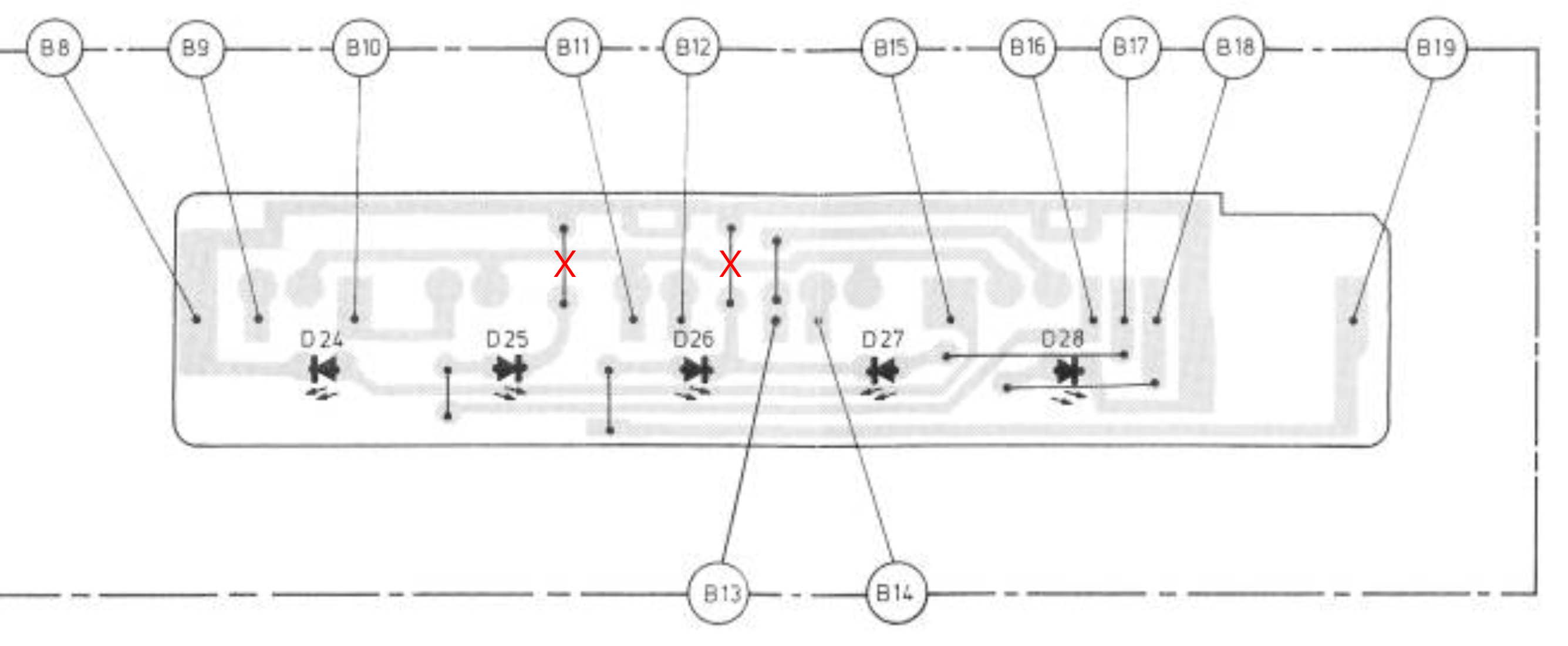
For the LEDs, we want to use charlieplexing, but the original LEDs have a common cathode configuration. Looking at the original PCB, we can simple change this by removing two jumper wires, as depicted in the figure below.
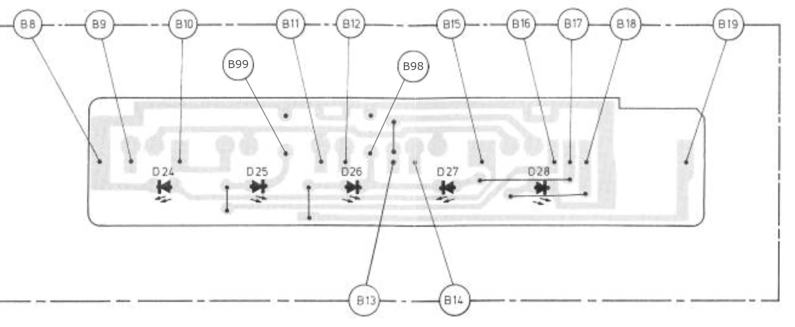
As the cathodes of D25, D26 and D27 are now not connected any more to the main board, we need two new connections (B99 en B98), as depicted below.
By combining the connections, we can create the charlieplexing circuit:
| Pin | Cathode (-) | Anode (+) | Connections |
|---|---|---|---|
| P40 | D25 | D26 D28 | B99 B18 B19 |
| P41 | D24 D28 | D27 D25 | B8 B16 B17 |
| P42 | D26 D27 | D24 | B98 B15 |
To make these connections, we will have a look at the main board. Three extra jumper connections are needed. Also depicted is the connections from B98 and B99. Two longer wires are needed: from A16 and A17 to the plain of A8 (at the left side of the picture).

We only need the three 180Ω resistors, which can probably also be populated on the original board (the orange resistors), so that leaves just three wires from the original board to the ESP32.
For the capacitive touch sensors, we only need one side of the connectors, and we might connect A11 to ground (not strictly necessary). This leaves:
| Pin | Connection | Function | P42 | P41 | P40 | |
|---|---|---|---|---|---|---|
| 11 | B10 | FM Preset 3 | Z | H | L | |
| 12 | B12 | FM Preset 2 | L | Z | H | |
| 13 | B13 | FM Preset manual | Z | L | H | |
| 14 | B14 | FM Preset 1 | L | H | Z | |
| 11+12 | B9 | FM Preset 4 | H | L | Z |
As we are missing one touch sensor, the current solution is to combine sensors of preset 2 and 3. So a user can select preset 4 by touching sensors 2 and 3. An alternative solution is to use Pin46 and free pin7. Pin46 is a boot strapping pin, so this is not really a very good solution :-(.
Volume, bass, treble and switches
The small PCB contains an analog filter network for volume, bass and treble. In the new situation, we want to do this in the digital domain, so we need to change quite a lot:
- The volume is a very special loudness tapped potentiometer (with 5 pins). We will only use the “regular” three pins, making it a normal potentiometer (we might need to compensate for the logaritmic behaviour);
- Bass and treble potentiometers are connected in an audio path, we need to change this so we can achieve a voltage from 0V to 3.3V.
- We want to use one of the switches as a selector
- The on/off switch can remain the same, but we have to be careful, as one site of the switch will receive unregulated 9V, and the other side will be connected to ground - switching this around will shorten the 9V to ground!
The figure below depicts the new circuit, with six extra jumper wires to create the new circuit.
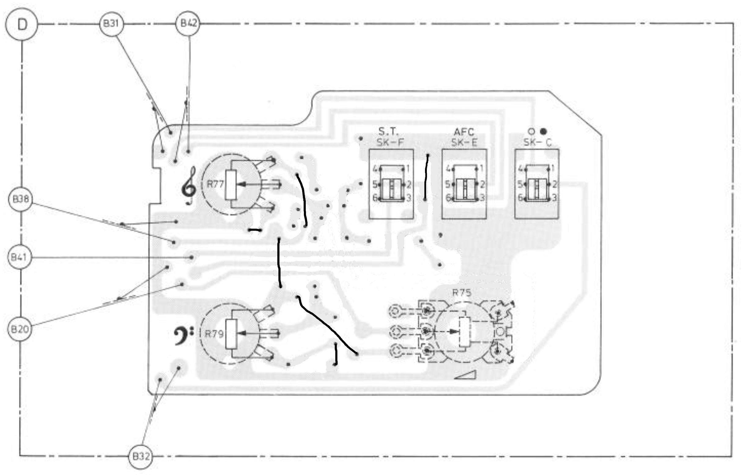
To make the connections, we can reuse most of the current connections. We leave the original wires B31 and B32 attached (these are audio wires with a ground shielding). The figure below depicts all traces.
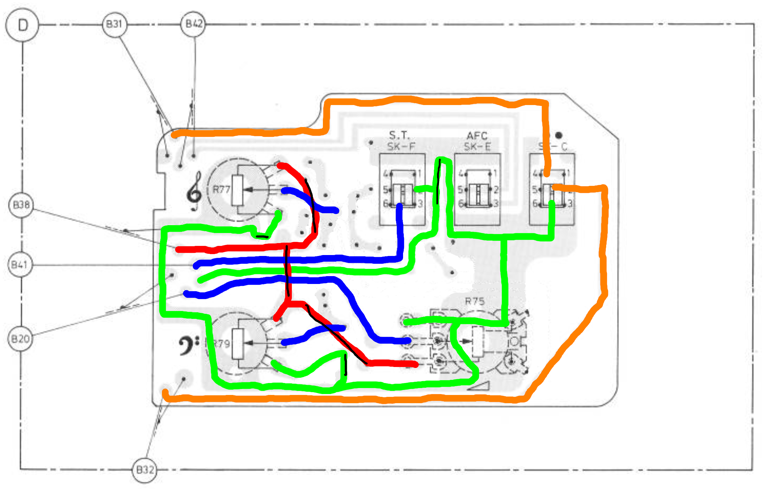
| Connector | Color | Pin | Function | |
|---|---|---|---|---|
| B31 | Orange | +9V | - | Unregulated power |
| B32 | Orange | OnOff | - | Power to the regulator |
| B20 shield, B38 shield | Green | GND | Ground | |
| B38 inside | Red | 3.3V | Reference voltage | |
| B20 inside | Blue | GPIO4 | Volume wiper | |
| New | Blue | GPIO5 | Treble wiper | |
| New | Blue | GPIO6 | Bass wiper | |
| B41 | Blue | GPIO10 | Switch to ground (needs pull-up at ESP32) |
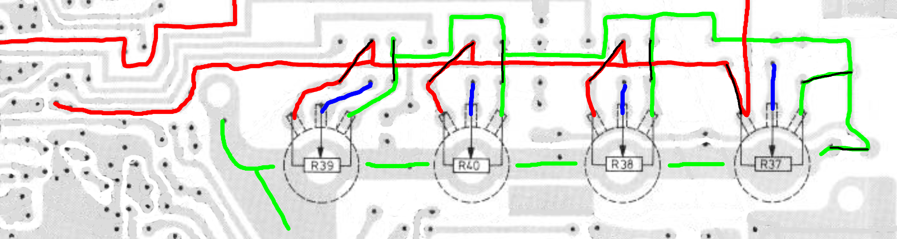
Tuners
As with the other potentiometers, we need to make some changes to the original circuit to make them behave like “regular” voltage-dialing potentiometers. Some jumper wires are needed, as depicted in the figure below. We will reuse the ground plain.
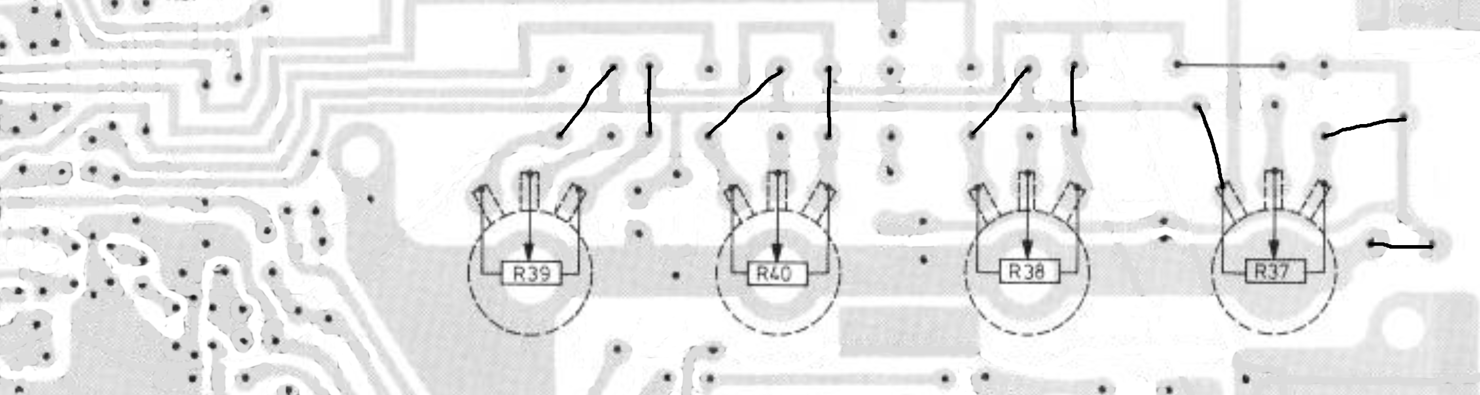
The 3.3V power path goes all the way to the (original) IC, but isn’t connected to anything else, so that’s OK. The four blue paths are the actual signal levels we need to measure.
Power
We will reuse the power amplifier part of the original radio. The figure below contains the remaining parts
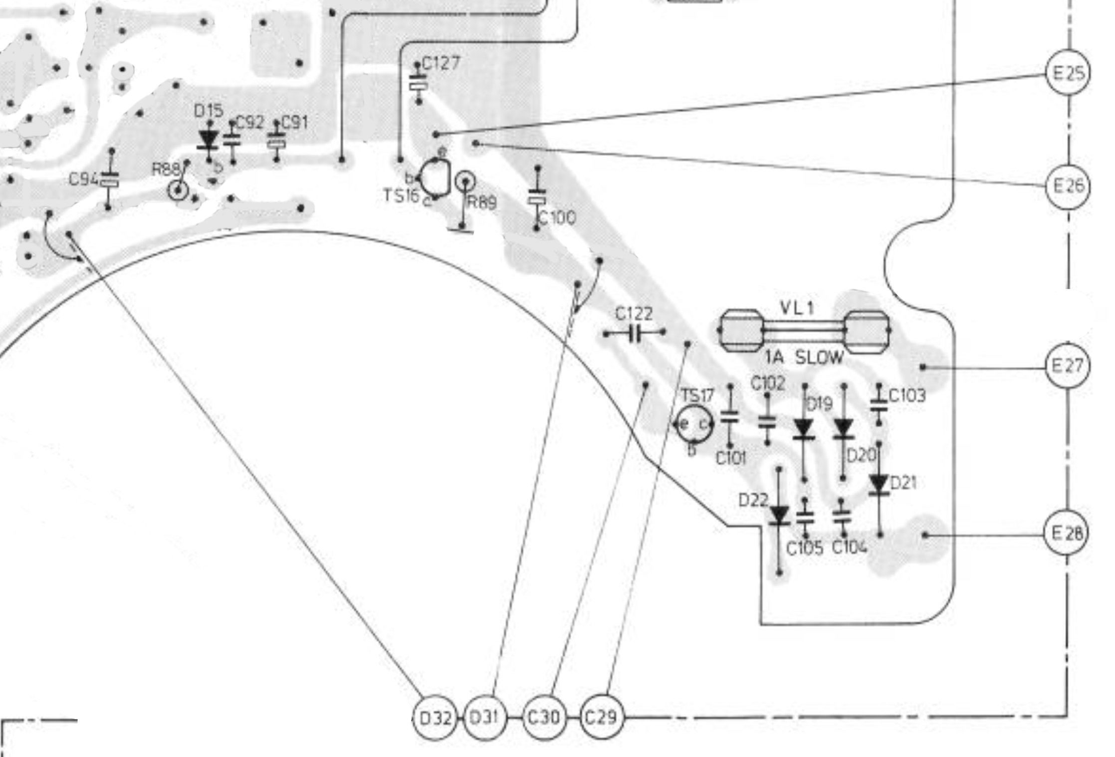
Everything from capacitor C100 to the right is actually part of the power circuit. D31 goes to the on/off switch, and D32 is the return path. The components to the left of C100 are part of a zener circuit to create the 6V power for the lamp, including a switching transistor (TS16).
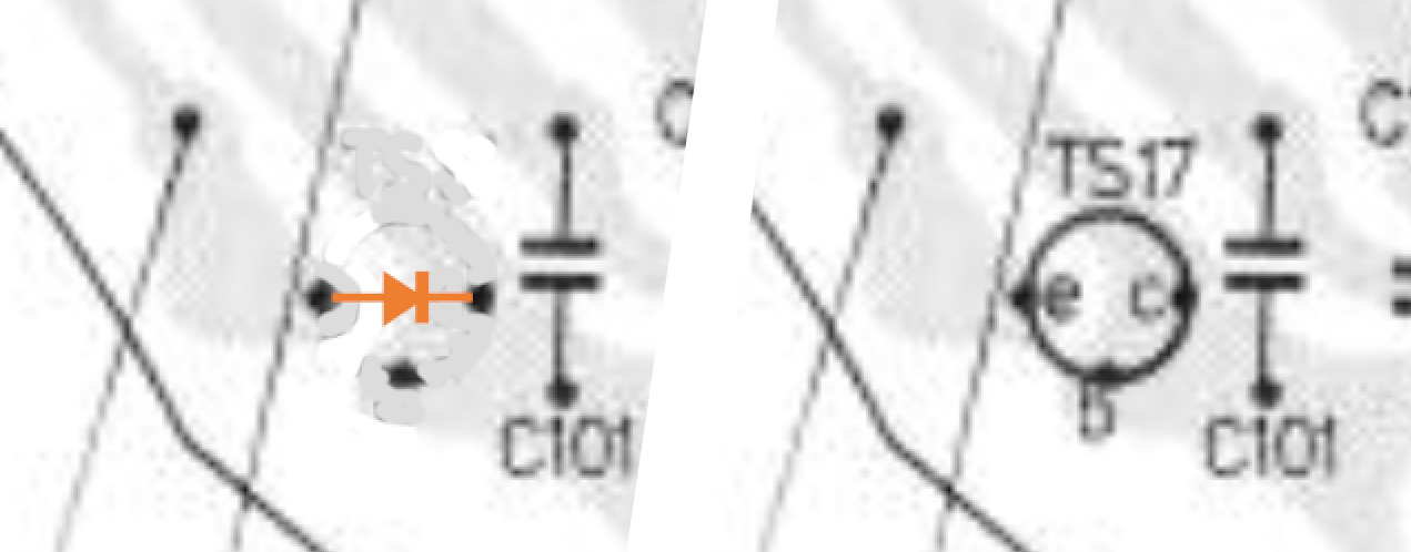
TS17 is used as a germanium diode (cathode and base combined), common for the time. This diode functions as an or-switch between the mains power and the battery (battery is switched of when mains power is used). We will replace this transistor with a modern skotsky diode, creating the same effect. This is depicted in the figure below.
| Connector | Function | Furth path |
|---|---|---|
| D31 | Unregulated power to the on/off switch | - |
| D32 | Unregulated power from the on/off switch | To the new regulator |
| C29 | Battery - | - |
| C30 | Battery + | - |
| E25 | Lamp (+) | To the lamp |
| E26 | Lamp (-) | To the lamp |
| E27 | AC blue wire | - |
| E28 | AC blue wire | - |
The battery wires are connected to the board via a snap-on connector, the AC wires are connected via a JST connector. The wires to the lamp are connected via a dupont connector.
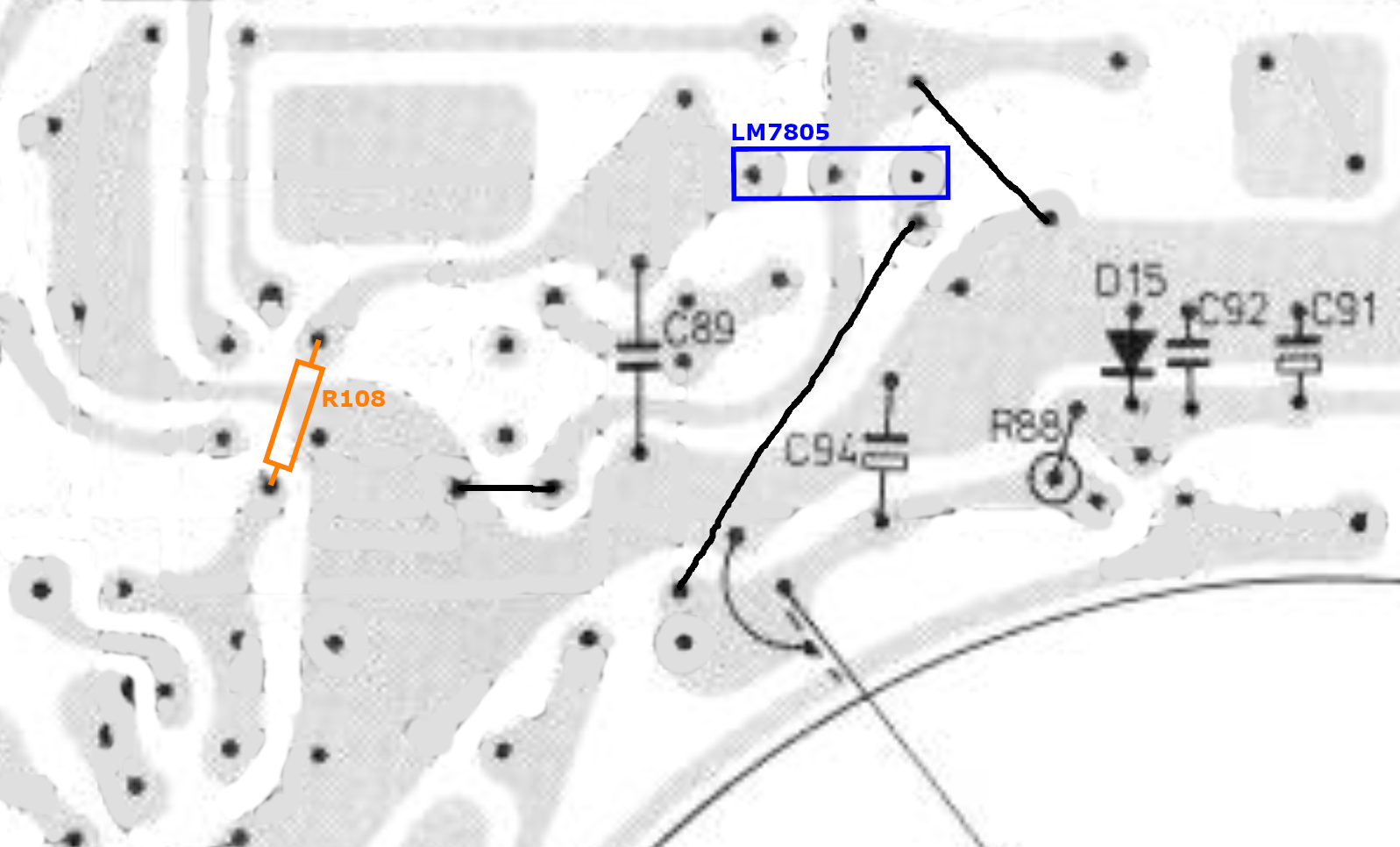
At the new regulator, we should also make a connection to the diode that is always on. This diode should be connected to the 5V rail via a ~1kΩ resistor.
With some smart placement, we can actually reuse this board for the LM7805 voltage regulator, so we don’t need an extra board. For this, we just need three jumper wires. As we also reuse the capacitors that are already there, we only need a small 100nF capacitor (C89) at the output side of the LM7805. The LED that is always on was originally connected to R108 and ground. This is now done at another part of the circuit. This is all depicted in the figure below.