ESP32 routing
The ESP32 S3 N16R8 is explained at randomnerdtutorials. The N16R8 is the S3 version with 8MB Octal PSRAM and 16MB Flash.
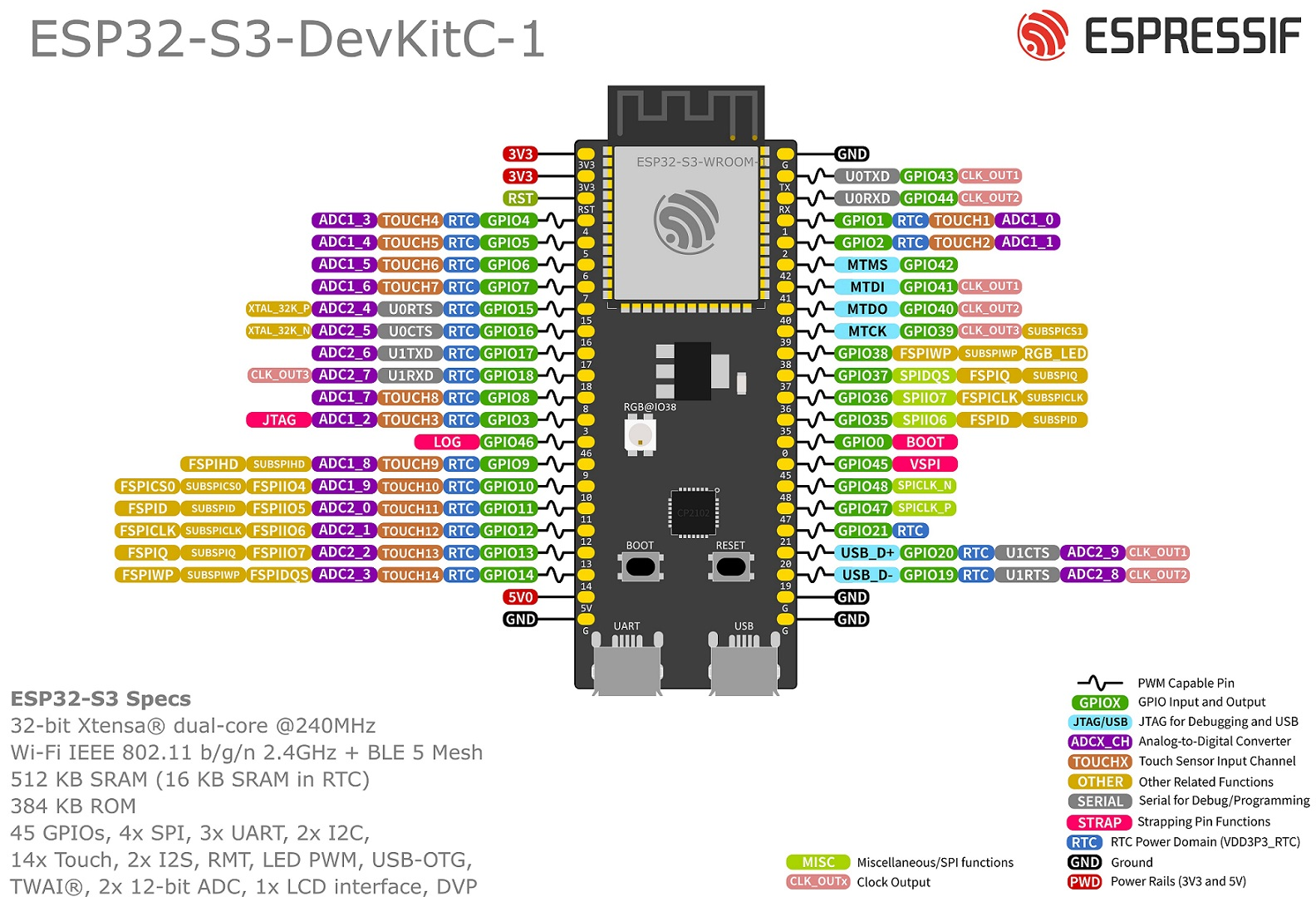
Important: this is version 1.1 of the board! In version 1.0 the RGB GPIO pin is actually pin 48, which I’m using for the I2S. Would you use version 1.0, the RGB LED will always be on. Don’t use version 1.0!
MAX98357A I2S audio board with 3W amplifier
The MAX98357A board is explained at adafruit
| DAC | ESP32 | Routing |
|---|---|---|
| DIN | DOUT (GPIO 21) | Digital out->in |
| BCLK | BCLK (GPIO 47) | Bit clock |
| LRC | LRC (GPIO 48) | Left/Right clock |
| GAIN | NC | Gain selection pin (Not Connected = 9dB gain) |
| SD | NC | Shutdown pin (Not Connected = stereo average) |
| GND | GND | Ground |
| Vin | 5V | Power, 5V |
The final project will power from a separate power supply (so 5V is actually not supplied from the ESP32, but directly from the power supply).
Because we have WiFI enabled, we cannot use ADC-2, we must use ADC-1 for the analog inputs. We also cannot use the ADC-2 pins for audio I2S. It does kinda work, but it interferes with the WiFI, so you have very bad WiFi reception.
The touch pin do work, however - probably because nothing is needed to be connected to sense the touching, and we only check once every 0.5 second.
Connection (left side)
| Pin | Function | Color | Connection | |
|---|---|---|---|---|
| 3V3 | 3V3 Power | Red | 3V3 Power to pots on small PCB | |
| 3V3 | 3V3 Power | - | 3V3 Power to pots on large PCB | |
| RST | Reset | - | - | |
| 4 | ADC1_3 | - | Volume | |
| 5 | ADC1_4 | - | Treble | |
| 6 | ADC1_5 | - | Bass | |
| 7 | ADC1_6 GPIO | - | Digital input pull-up for lock switch | |
| 15 | ADC2_4 Touch | Green | FM preset 4 selector | |
| 16 | ADC2_5 WiFi | - | - | |
| 17 | ADC2_6 WiFi | - | - | |
| 18 | ADC2_7 WiFi | - | - | |
| 8 | ADC1_7 | White | FM preset 1 dial | |
| 3 | ADC1_2 | Green | FM preset 2 dial | |
| 46 | LOG | - | - | |
| 9 | ADC1_8 | Blue | FM preset 3 dial | |
| 10 | ADC1_9 | Purple | FM preset 4 dial | |
| 11 | ADC2_0 Touch | Grey | FM preset 3 selector | |
| 12 | ADC2_1 Touch | Brown | FM preset 2 selector | |
| 13 | ADC2_2 Touch | Blue | FM preset MAN selector | |
| 14 | ADC2_3 Touch | Purple | FM preset 1 selector | |
| 5V | 5V Power | Orange | 5V from regulator | |
| GND | Ground | Black | GND from regulator |
A problem can occur with GPIO-3 with respect to the setting of Preset 2 dial, as this pin is used during boot.
Connections (right side)
| Pin | Function | Color | Connection |
|---|---|---|---|
| GND | Ground | - | - |
| 43 | TX | - | - |
| 44 | RX | - | - |
| 1 | ADC1_0 | Brown | FM tuning |
| 2 | ADC1_1 | Grey | FM fine tuning |
| 42 | GPIO | Orange | FM preset LEDs |
| 41 | GPIO | Yellow | FM preset LEDs |
| 40 | GPIO | Blue | FM preset LEDs |
| 39 | GPIO | White | FM tuning LED |
| 38 | RGB LED | - | - |
| 37 | PSRAM | - | - |
| 36 | PSRAM | - | - |
| 35 | PSRAM | - | - |
| 0 | BOOT | - | - |
| 45 | VSPI | - | - |
| 48 | GPIO | - | Audio I2S LRC |
| 47 | GPIO | - | Audio I2S BCLK |
| 21 | GPIO | - | Audio I2S DOUT |
| 20 | USB | - | - |
| 19 | USB | - | - |
| GND | Ground | - | - |
| GND | Ground | - | To miniboard |
I’m actually not sure if GPIO 35, 36 and 37 are used for PSRAM, so maybee I can use these for input control??
