ESP32
The ESP32 devboard we’re using has most pins of the ESP32 exposed, so we have a lot of GPIO’s available (which we will need!).
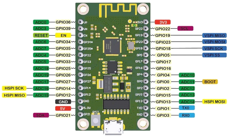
The table below gives all the inputs we need
| ESP32 | VFD | Key pins | Slider pins | Description |
| 5V | - | - | - | 5V input from 5V regulator |
| GPIO2 | - | - | - | Test LED (blinking) |
| - | 1 | - | - | Filament F- |
| 3.3V | 5 | - | - | Vdd, same for ESP32 Vdd |
| - | 8 | - | - | Vdisp-ON, to enable Vdisp, via the NPN-PNP high side, dual power rail transistor circuit |
| ? | - | - | - | Vdisp_ON signal from ESP32, via transistors |
| GND | 7 | - | - | GND common ground (V-) |
| - | 8 | - | - | OSC circuit for VFD |
| ? | 9 | - | - | RST reset pin VFD |
| GP5 | 10 | - | - | CS Chip Select SPI |
| GP18 | 11 | - | - | CLK Clock for SPI (VSPI) |
| GP23 | 12 | - | - | DIN Data input for SPI (VSPI MOSI pin on ESP32) |
| GP19 | - | - | - | VSPI MISO pin on ESP32, not usable as it is read by the SPI library |
| - | 45 | - | - | Filament F+ |
| TX0 | - | - | - | Serial port |
| RX0 | - | - | - | Serial port |
| GP16 | - | - | - | RX UART Serial for audio module |
| GP17 | - | - | - | TX UART Serial for audio module |
| GP21 | - | - | - | SDA I2C bus |
| GP22 | - | - | - | SCL I2C bus |
| GP13 | - | 8 | - | Key scan output |
| GP4 | - | 9 | - | Key scan output |
| GP25 | - | 10 | - | Key scan output |
| GP26 | - | 11 | - | Key scan output |
| GP27 | - | - | 5 | Slider scan output |
| GP32 | - | - | 6 | Slider scan output |
| GP33 | - | - | 7 | Slider scan output |
For the 12 input pins, we could use two daisy-chained 74HC165 as described here => paralel to serial. These chips have internal pull-down resistors, so we don’t have to worry about that.
…but we finaly settled for the MCP23017. Communication is over the I2C bus, this chip is configured in “input” mode, with pull-up resistors.
GP16 and GP17 are used for the serial communcation with the audio module, we will use the DFRobot Voice Module DFR0534