Original calculator insides
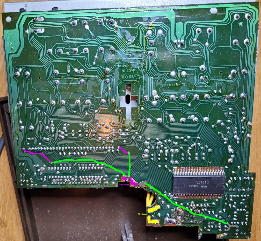
Analysing the original calculator gives very interesting information how these calculators were made originally. An important clue is that these calculators are positive ground, so V+ is actually the ground, and V- the power. This also means that all diodes are in the oposite direction as you would expect!
The original IC does four things at the same time: key scanning, controlling the VFD display, controlling the printer and, off course: calculating. The IC has 34 pins, so lots of possibilities, but these pins are used in a particular matrix fashion.
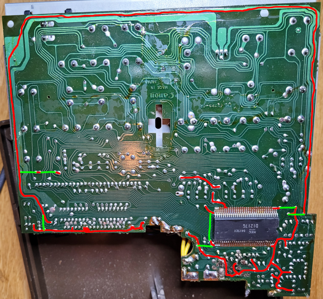
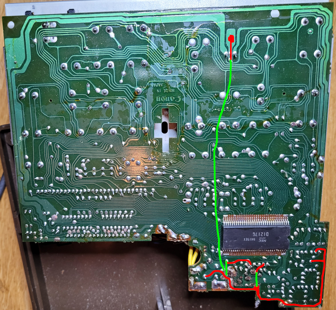
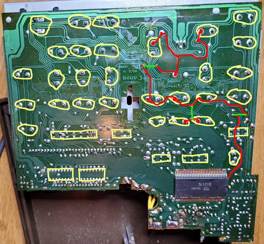
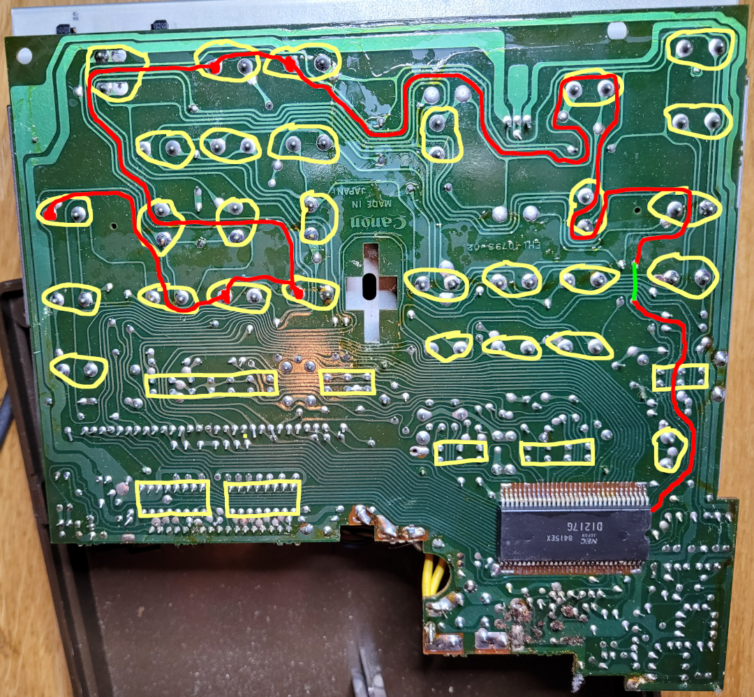
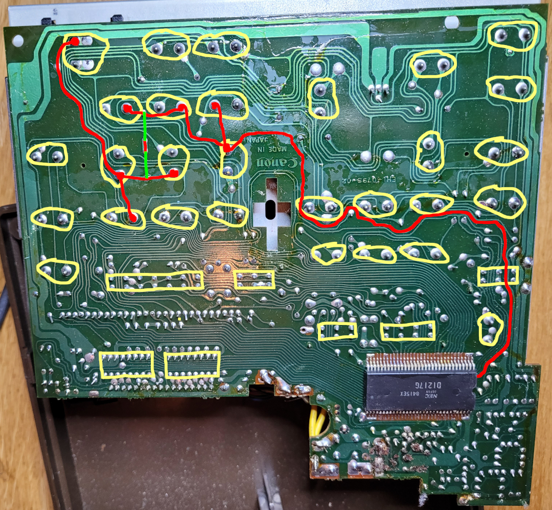
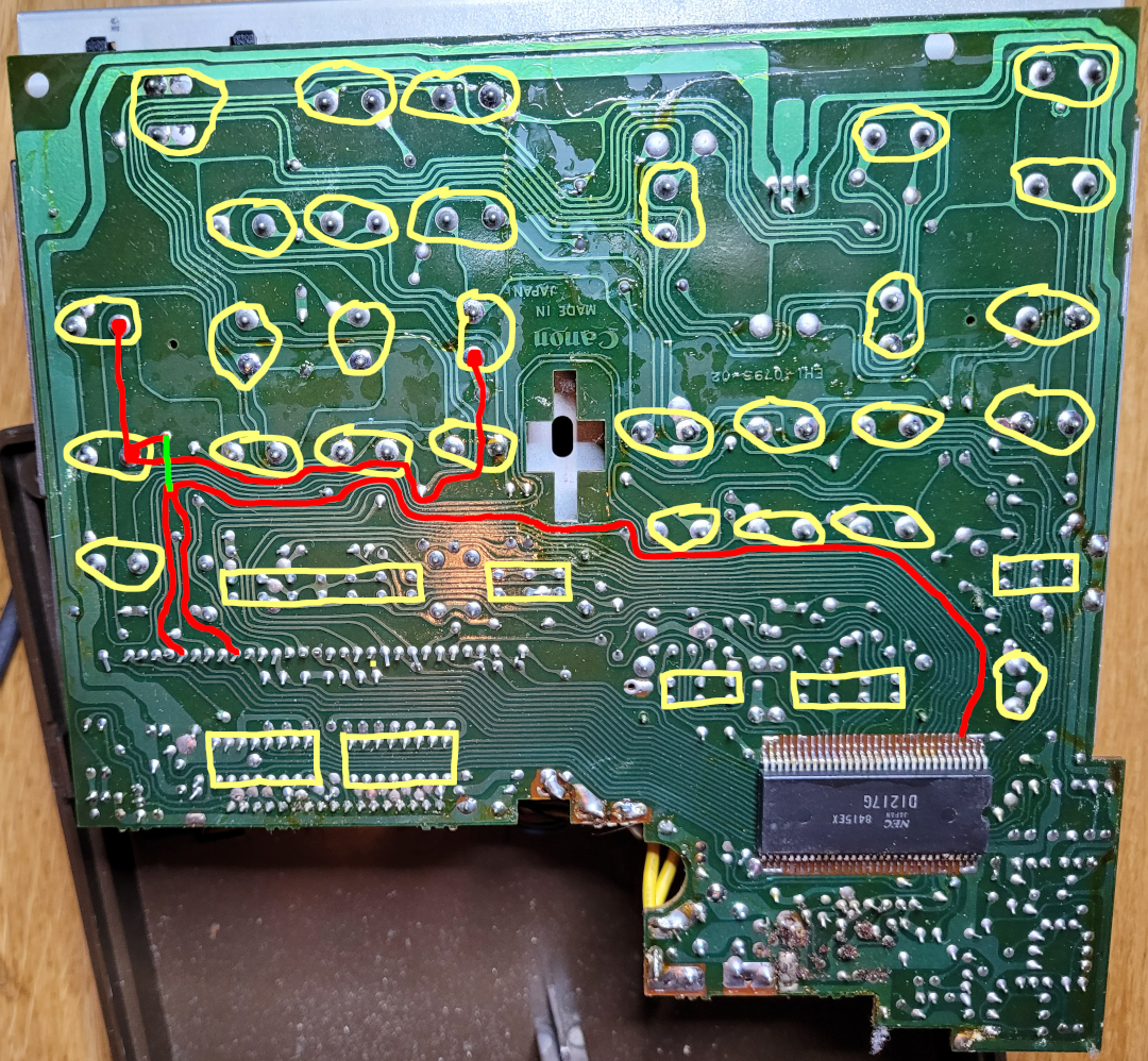
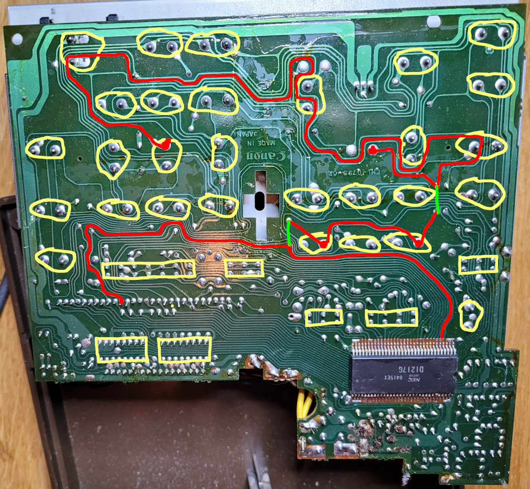
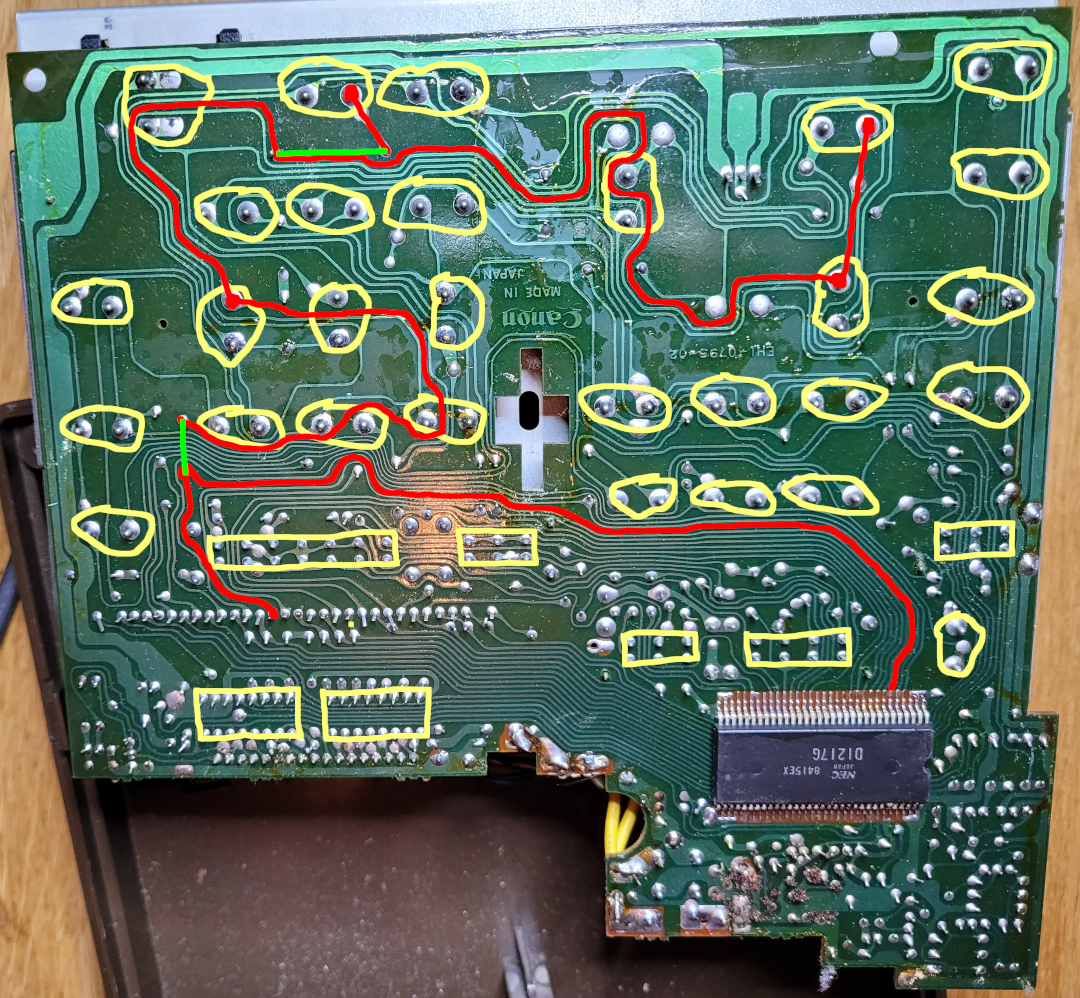
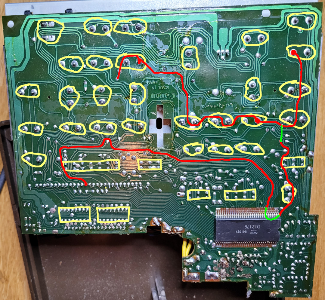
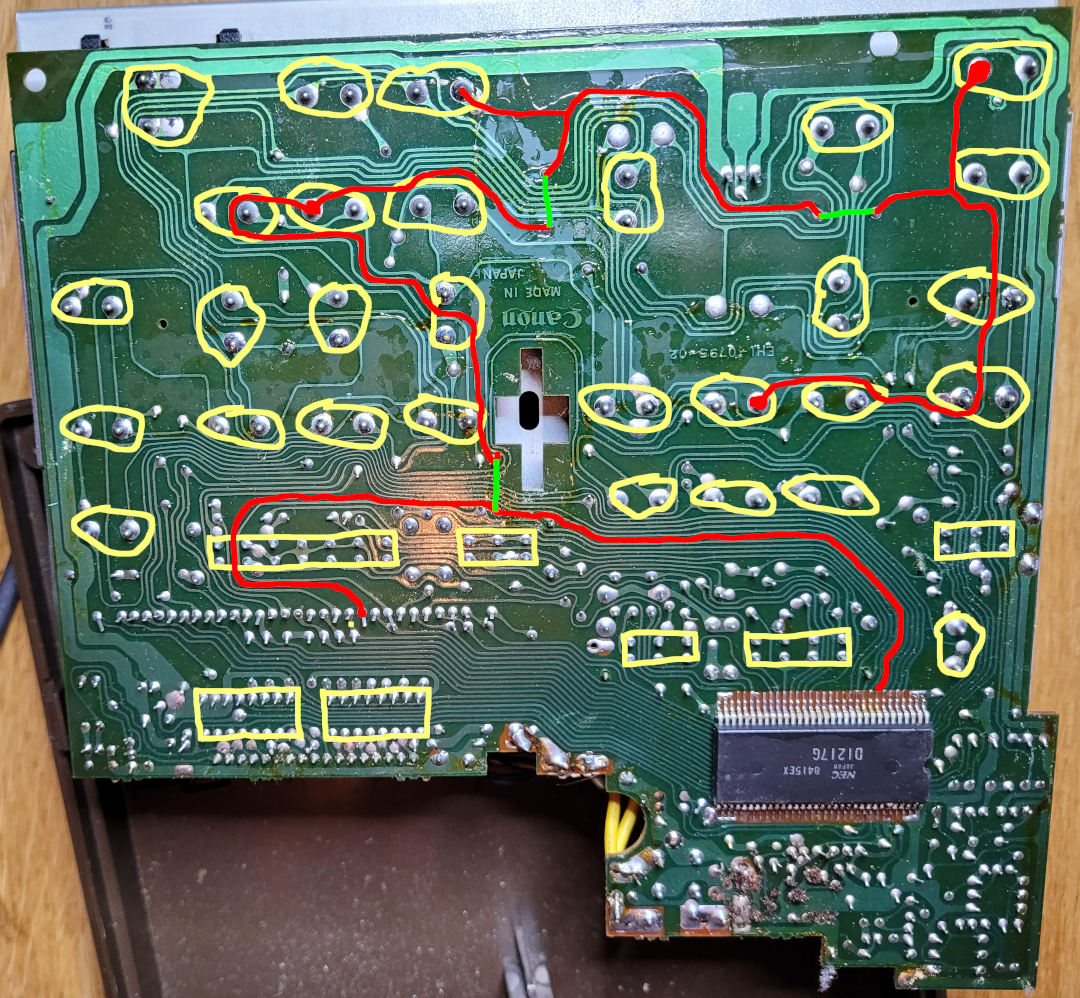
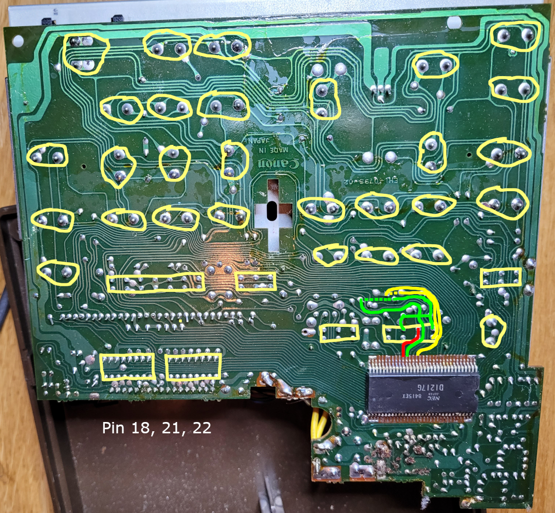
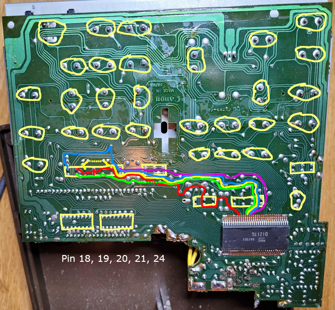
The pictures below give the traces on the PCB for every pin of the IC, which makes it possible to find all the functions of the pins, as the datasheet for this IC is not to be found on the internet… (such a shame!)
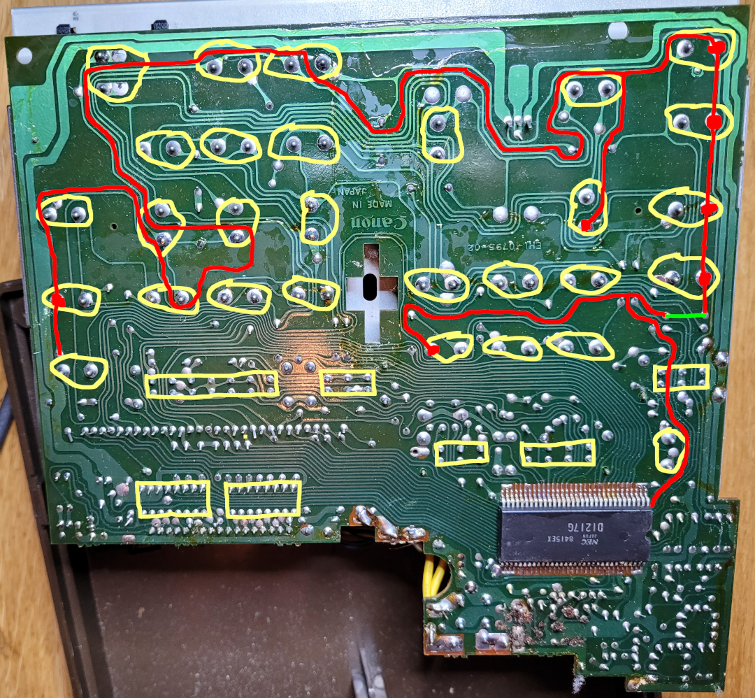
From this, we can find out how the key matrix works. We don’t have to find out how the VFD or printer controller works, as we will use a new VFD which has a build in controller.
Using a scope, we can analyse how the circuit works. Interesting, the scanning of the keys uses the same circuit as the display! The display is multiplexed, and during this cycle, the keys are scanned - so briefly that this is not visible on the VFD.
PCB Traces
The PCB traces are grouped by their function with regard to the controlling IC.