Original calculator power
The original power is quite interesting. A special transistor is used that is particularly suited for a VFD display, as it has a centre tap and two AC 3.8V voltage wires, plus two seperated wires for ground and 34V AC. A bridge rectifier gives a DC signal, using a big 3300uF capacitor to smooth out the signal. This -34V AC is used unregulated as the voltage for the printer and is further regulated to 24V and 11V, using a traditional zener-transistor configuration.
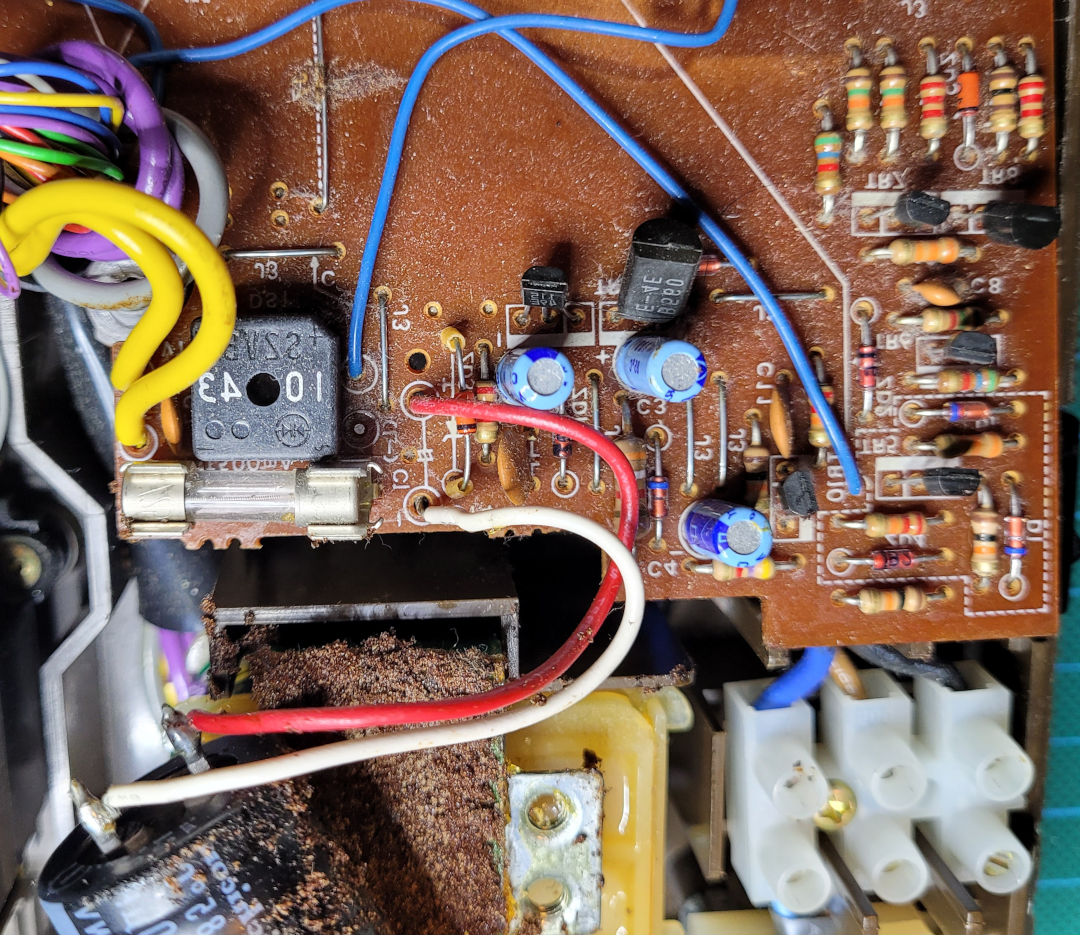
Front side (components)
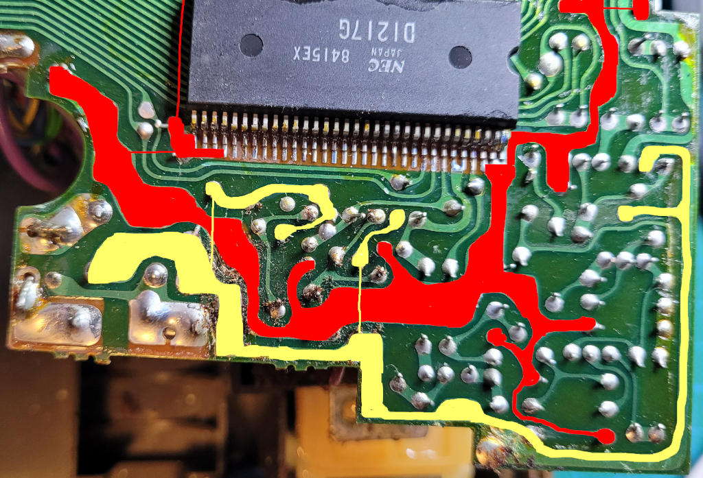
Back side (traces)
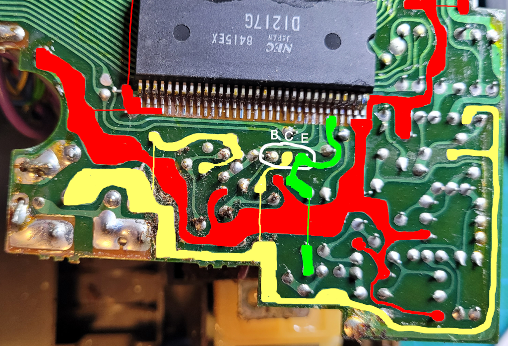
Circuit
The -34V is send to two zener-transistor circuits to regulate the voltage to -24V and -11V.
The -24V circuit uses a small 2sa115 PNP Si transistor. The maximum collector current of this transistor is 20mA. The maximum power dissipation for such a small transistor is 0.05W according to the datasheet. With a voltage drop of 10.7V over the transistor, this means that the maximum current will be 4.7mA. This is not much, but the anode and grid are voltage-driven, they don’t use much current.
Then -11V circuit uses a larger 2SB560 PNP Si transistor. The maximum collector current of this transistor is 700mA. The maximum power dissipation for this transistor is 0.75W according to the datasheet. With a voltage drop of 23.7V over the transistor, this means that (only) 32mA is available. This will probably be more than enough for the MCU of the original calculator.
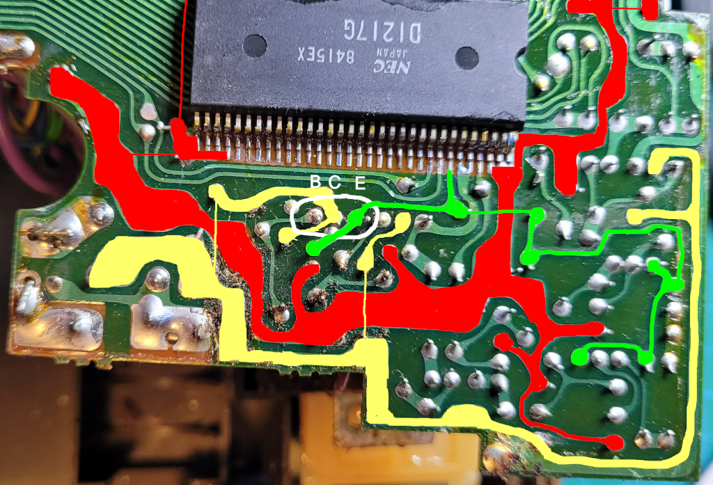
Power Pins
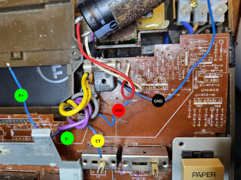
The remnants of the power circuit. The pins that we need are labeled:
- Black GND: The ground connection (originaly this was the -34V pin (positive ground), now we use negative ground)
- Red 34V: The DC voltage after the rectifier and the 3300uF capacitor (we might add some more filtering capacitors!)
- Yellow CT: The center tap for the filament AC power. We use this one to bias the filament.
- Green F+/F-: The 1.7 AC filament voltage (referenced to the center tap). (F- is not a blue wire, but the cut-off connection)