Calculator key matrix
If a key is pressed, a cell in the matrix connects two pins together. So by scanning one side of the matrix and reading the values of the other side of the matrix, we can found out which key is pressed. As this will only happen when the key is pressed, we can use interrupts.
This doesn’t work for the sliders and the printer-toggle button. But these also have quite a complex system to now what value is displayed so not a lot of pins are used.
Keys
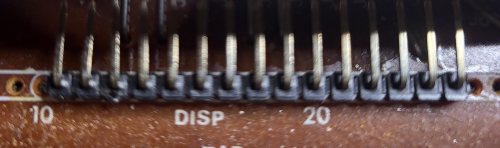
Pin and key numbers correspond to the VFD pins and the key numbers as depicted on the insides page. The pin numbers 11-25 correspond to the VFD pins as depicted in the image below.
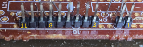
The Key numbers correspond to the pin numbers on the pins near the board edge, as depicted in the image below:
| Pin 7+11 | Pin 9+20 | Pin 13 | Pin 15 | Pin 22 | Pin 24 | Pin 25 | Pin 16 | |
| Key 2 -> (pin 11) |  |
 |
 |
 |
 |
 |
 |
|
| Key 3 -> (pin 10) |  |
 |
 |
 |
 |
 |
 |
|
| Key 4 -> (pin 9) |  |
 |
 |
 |
 |
|||
| Key 5 -> (pin 8) |  |
 |
 |
 |
 |
 |
 |
 |
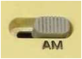
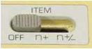
Sliders
The sliders are always in a particular state, so we just want to scan them if we need to. All sliders have one setting that doesn’t correspond with any matrix value. This is the “default” value that should be set if no value is found. Pin numbers correspond to the pin numbers on the pins near the board edge, as depicted in the image below:
| Pin 3 | Pin 1 | Pin 2 | Pin 4 | Pin 3+4 | Pin 2+4 | |
| Pin 5 | 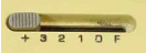 F F |
+ |
2 |
1 |
3 |
|
| Pin 6 |  |
 |
 |
|||
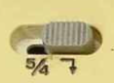
| Pin 7 | 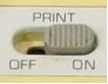 |
 |
 n+ n+ |
n+/- |
As the pin connections use diodes, the flow should be from pins 5-7 (output pins, V+) to pins 1-4 (input pins, V-). The diodes will also mess up the resistance value if you probe the connections, but you can probe, as the value will drop from infinity to a lower value (but not 0V).