Full board PCB
The fritzing sketch below depicts the PCB for the full board, combining the PCB’s for the Silicon, Germanium and Tube boosters.

The board fits nicely in a 31x26 board (sized 9x7 cm), which just gives enough room so the foot switches can be beneath the board.
This PCB corresponds to the circuit below.

The picture below gives all the components placed on this board. Only the transistors are left out. The height of the board (inclusive the PCB) is 16mm, which give a 17mm space for the “top” components, which will be enough.
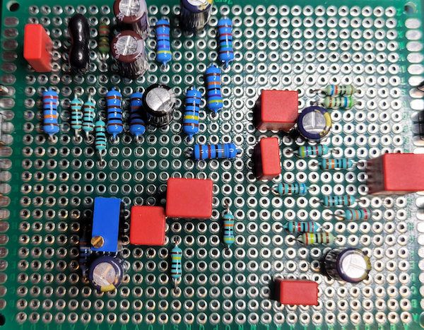
NB: The top left capacitors (the red one and the mylar one) will not be placed on the PCB, but directly soldered to the capacitor selector switch (tube booster). The rightmost capacitor (C11) and R15 (120kΩ) will also be soldered directly to the capacitor selector switch. C11 (10nF) will be accompanied by a 5nF capacitor to change the input capacitor of the Si treble booster.