Tube PCB
The picture below is a picture of the actual PCB from the Banana booster (rev 5).
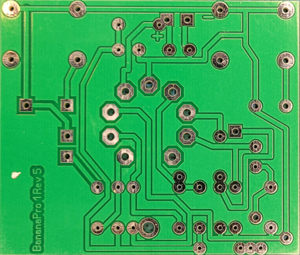
There are some problems with this PCB:
- It is quite large (75.1mm x 64.0mm);
- The position of the tube is too low;
- Only one “filter”-capacitor: we want two, with a selector switch.
We will create our own PCB, and use a separate socket for the tube. The fritzing sketch below depicts the original PCB, as expected, the circuit is exactly like the circuit in the theory section.


With the new PCB, we will remove the input and output sockets from the PCB, as well as the tube itself. This will clean up the PCB a lot, so it has a much smaller footprint. But we will need a lot more connections.
The fritzing sketch is the resulting PCB, and this sketch contains the connection routing.

A 16x12 grid is needed for this PCB (40.64mm x 30.48mm), almost half the size of the original.

