Buiding the dXFM2
Building of the dXFM2 took a lot of testing, finding stuff out and putting it in a case. I’ll start with just a couple of pictures from the guts of the case, at this moment most of the building information can be found in the Github repo.
Most hardware is attached to the aluminium front of the case, making it easier to install everything.
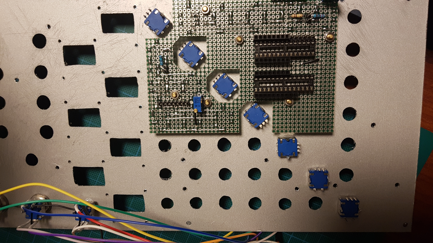
The encoders are attached to the front plate. I used PCB style encoders (for lack of better ones), and just soldered jumper wires to them, isolated with head shrink tubes. The attached panel (using M3 stand-offs) contains some LED buttons, but also the IC sockets for the encoder multiplexers. I had to saw it into this particular shape to give room for the encoders and still have some structural integrity.
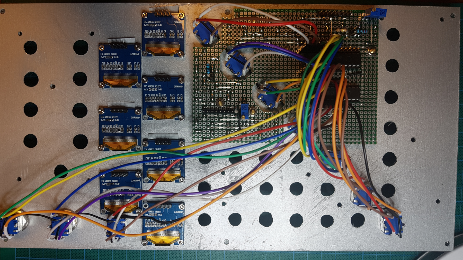
I used easy to get, regular OLED screens. To have them position tightly to the front plate, I bolted them to the plate, using (very tiny) M2 screws. This was a very precise operation, because I also made a PCB that is connected to all of these OLED screens (the PCB contains the OLED I2C multiplexer).
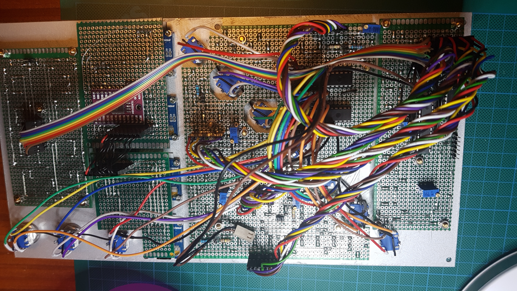
The panel on the right contains the LED matrix IC, so a lot of cables are going from the different panels to this matrix. It might have been easier to make one big PCB, but as this is actually a prototype, this way it was easier to test every individual component. The downside is a lot of wires…
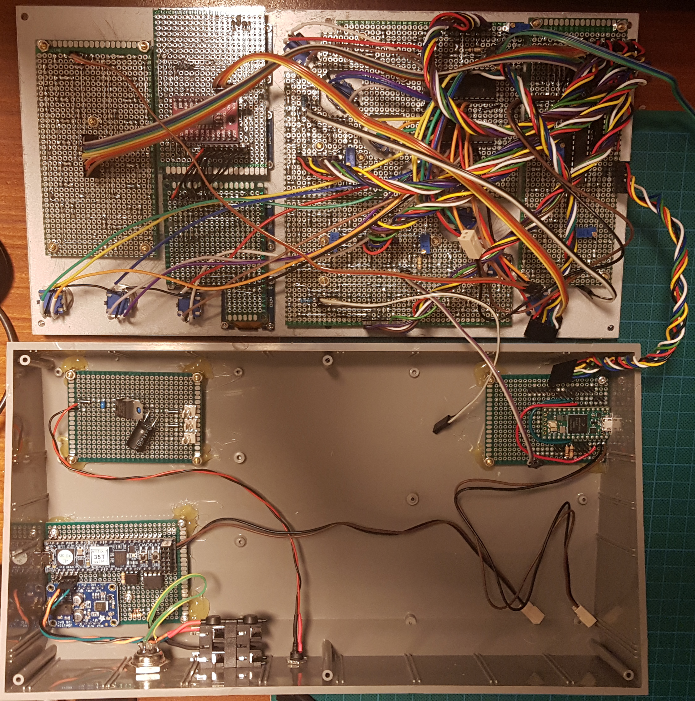
This last picture tells the whole story. In the case, the top left PCB contains the PSU board (just some diodes, the LM7805 voltage regulator, the filter capacitors and connectors to the individual boards). Bottom left is the XFM2 board as specified by René. Top right is the PCB for the Teensy controler. Not all connections are made, but any connection from the front plate will go the the teensy. From the teensy a serial connection is made to the XFM2 board. As you can see, I made another audio out connection from the XFM2 board, to make it more easy to connect two mono jack cables directly into a DI.
Both USB board are still accessible from outside the case, which makes it possible to reprogram the synth without having to take it apart.